For ages, Candles have been of great use; it has been directing people at night even before Edison concocted the thought of bulbs. Today, from Churches to kitchens, Candles are utilized not exclusively to give light when required but also to indicate the aesthetics and warm feeling.
Thus, in this instructional exercise, we will make a “flameless electronic candle” by utilizing some hardware components. Further, this Smart Candle will consequently turn on at night and close itself off during the day. For ages, Candles have been of inconceivable use; it has been directing individuals at night even before Edison devised the idea for bulbs.

Hardware Components
The following components are required to make Smart Electronic Candle Circuit
| S.no | Component | Value | Qty |
|---|---|---|---|
| 1. | IC | LM358 | 1 |
| 2. | LDR (Photoresistor) | – | 1 |
| 3. | Resistor | 1K, 1M, 10K Pot | 1, 1, 1 |
| 4. | Card sheet and Perfboard | – | 1 |
| 5. | Female DC Power Jack and 12V Adapter | 12V | 1 |
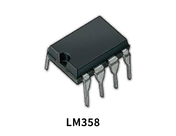
LM358 Pinout

For a detailed description of pinout, dimension features, and specifications download the datasheet of LM358
Smart Electronic Candle Circuit

Circuit Operation
Now, let’s see how the candle can work. As we already know, the LDR’s resistance increases to megaohm in the dark and decreases to just a few hundred ohms with increased light intensity. So the voltage over a non-inverting signal in the light as the resistance is very low relative to the inverting terminal, due to the 10 K attached potentiometer.
So the output voltage is low in this case, too, so that the LED is not triggered. But the resistance rises to megaohms in the event of darkness, which is already high relative to the 10 K potentiometer so that the LED is glowing. Sensitivity is manipulated by adjusting the potentiometer.
Applications and Uses
This Smart Electronic Candle is used to give light when needed.


