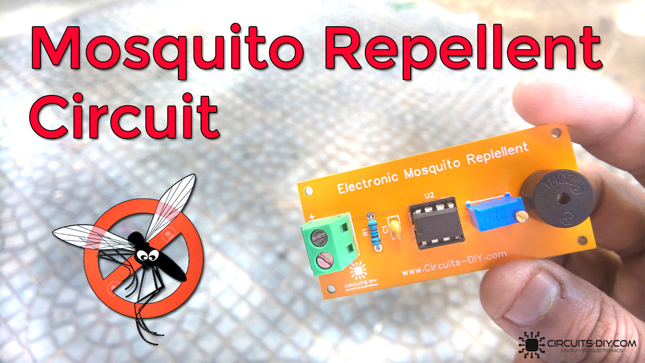
An insect repellent or a mosquito repellent is a simple electronic circuit that repels small insects such as mosquitoes & flies on the principle that insects can be repelled by exposing them to sound frequencies in the ultrasonic region (above 20KHz). Insect repellent circuits are cheap & easy to design. So, in today’s tutorial, we will go over a step-by-step procedure on how to build an insect repellent circuit using NE555 timer IC.
The heart of this circuit is a NE555 precision timer IC. The IC possesses an oscillation frequency ranging from 670 to 680Hz. Here, this NE555 timer acts as an astable multivibrator An astable multivibrator is a free-running oscillator that switches continuously between its two unstable states. With no external signal applied, the transistors alternately switch from cutoff to saturation state at a frequency that RC time constants of the coupling circuit determine. If these time constants are equal (R and C are equal) then a square wave will generate with a frequency of 1/1.4 (RxC). Hence, an astable multivibrator is also a pulse generator or a square wave generator.
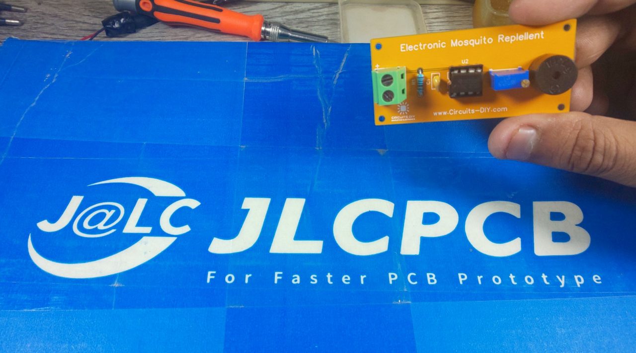
JLCPCB is the foremost PCB prototype & manufacturing company in china, providing us with the best service we have ever experienced regarding (Quality, Price Service & Time).
Hardware Components
The following components are required to make Mosquito Repellent Circuit
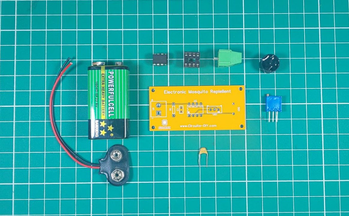
| S.No | Component | Value | Qty |
|---|---|---|---|
| 1) | Timer IC | NE555 | 1 |
| 2) | Piezo Buzzer | 5V | 1 |
| 3) | Potentiometer | 10K Ohm | 1 |
| 4) | Resistor | 1K Ohm | 1 |
| 5) | Capacitor | 0.1uF | 1 |
| 6) | DC Battery | 9V | 1 |
| 7) | Battery Clip | – | 1 |
| 8) | Breadboard | – | 1 |
| 9) | Jumper Wires | – | As per need |
NE555 IC Pinout

For a detailed description of pinout, dimension features, and specifications download the datasheet of 555 Timer
Mosquito Repellent Circuit
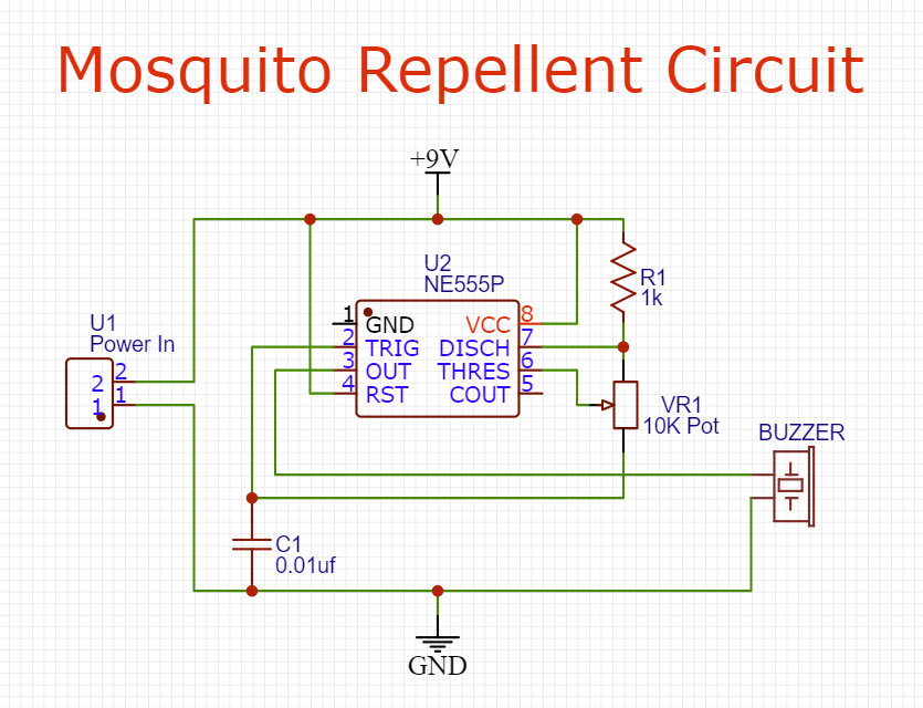
Useful Steps
1) First of all, solder the 8 – pin IC base on the PCB board.
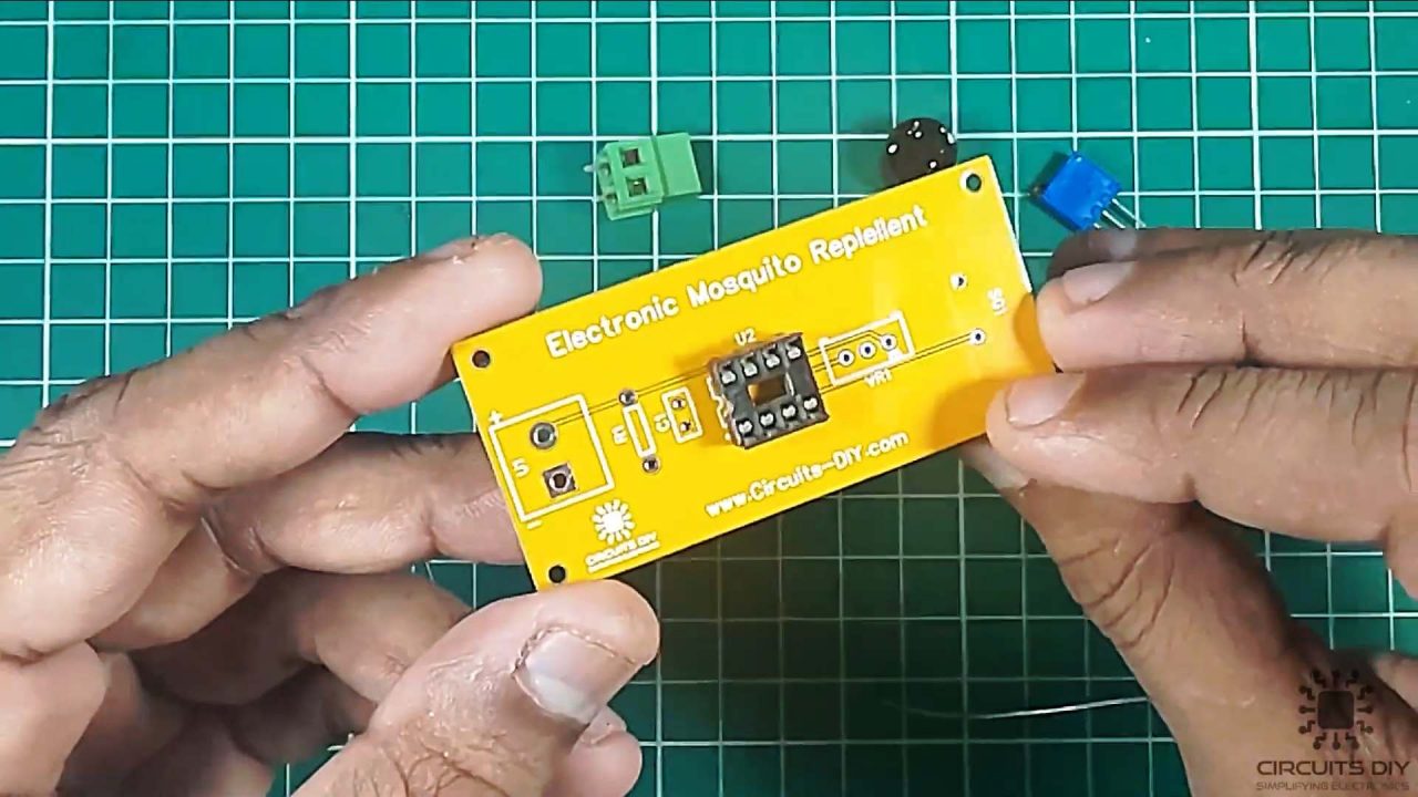
2) After that, place the 555 timer IC in the 8 – pin IC socket.
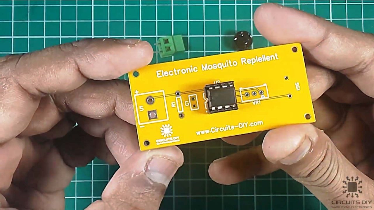
3) Solder the 10K pot on the PCB board.

4) Solder the 1K Ohm resistor on the PCB board

5) After that, solder the 0.01uF capacitor on the PCB board.
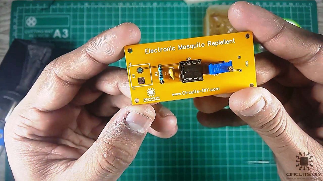
6) Solder the 5V buzzer on the PCB board.
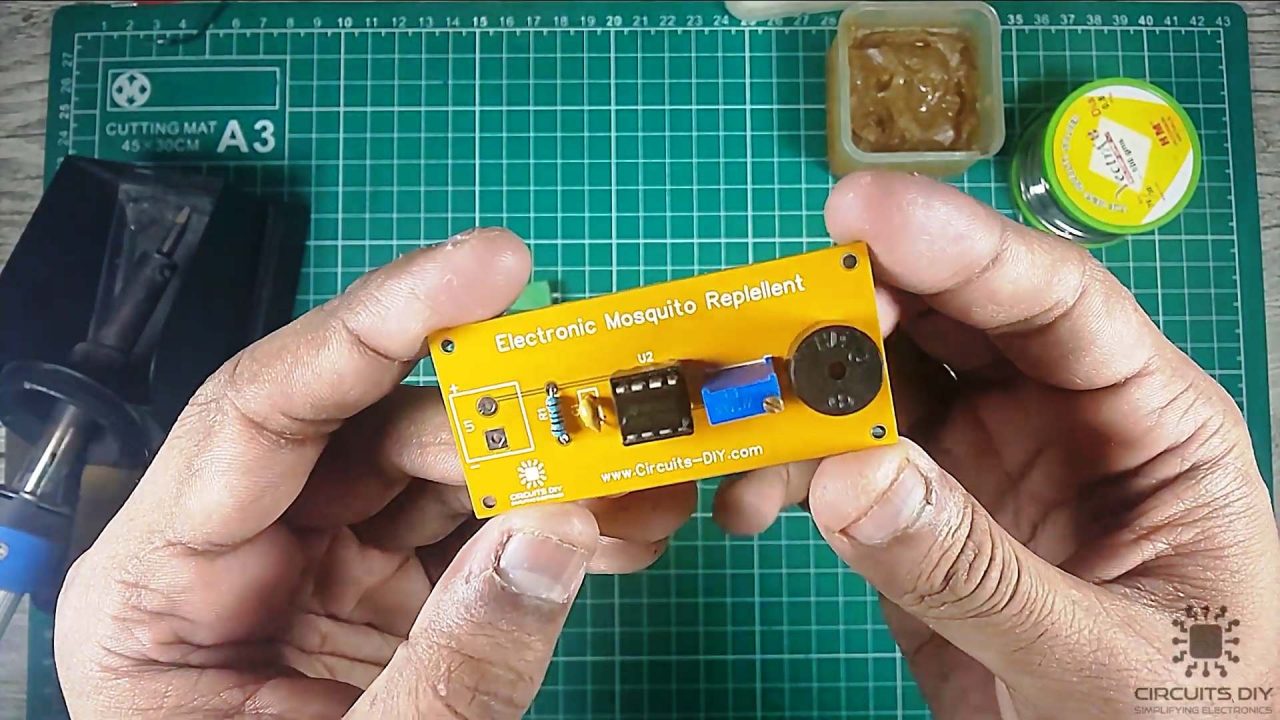
7) After that, solder the input terminal block connectors on the PCB board.
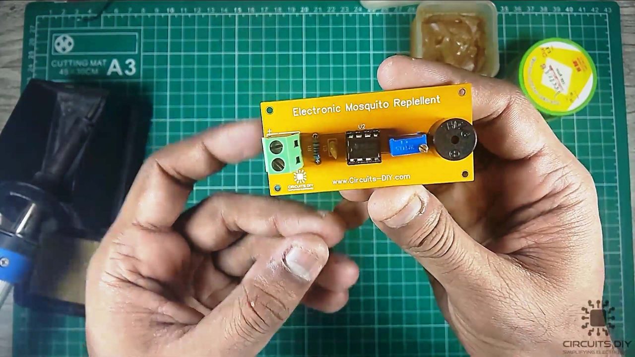
8) Power up and test the circuit using a 9V Battery.

Working Explanation
The working of this circuit is fairly simple. Here the NE555 precision timer is running in astable mode, hence producing a square wave output at a constant frequency set by the RC time constant. In order to effectively repel mosquitos, we need to generate a sound signal in the ultrasonic region. We can do this by simply altering the oscillation frequency of the astable multivibrator through the 10K preset pot. You can use a 5V – 9V DC battery to power this circuit.
Applications
- Usually used to repel small insects such as mosquitos & flies.


2 thoughts on “Simple Insect Mosquito Repellent – Electronics Projects”
Comments are closed.