In this tutorial, we are making a Hall effect sensor switch circuit. The circuit is useful and has various magnetic field detection applications. Its main component is a hall effect sensor. A hall effect sensor is a magnetic field sensor and it provides an output voltage directly proportional to the detected magnetic field. It comes in a TO-92 package and a surface mount package. Basically, it comes in a complete package of a hall sensor, regulated power supply, trigger circuit, and temperature stabilizer circuit in a single three-terminal chip.
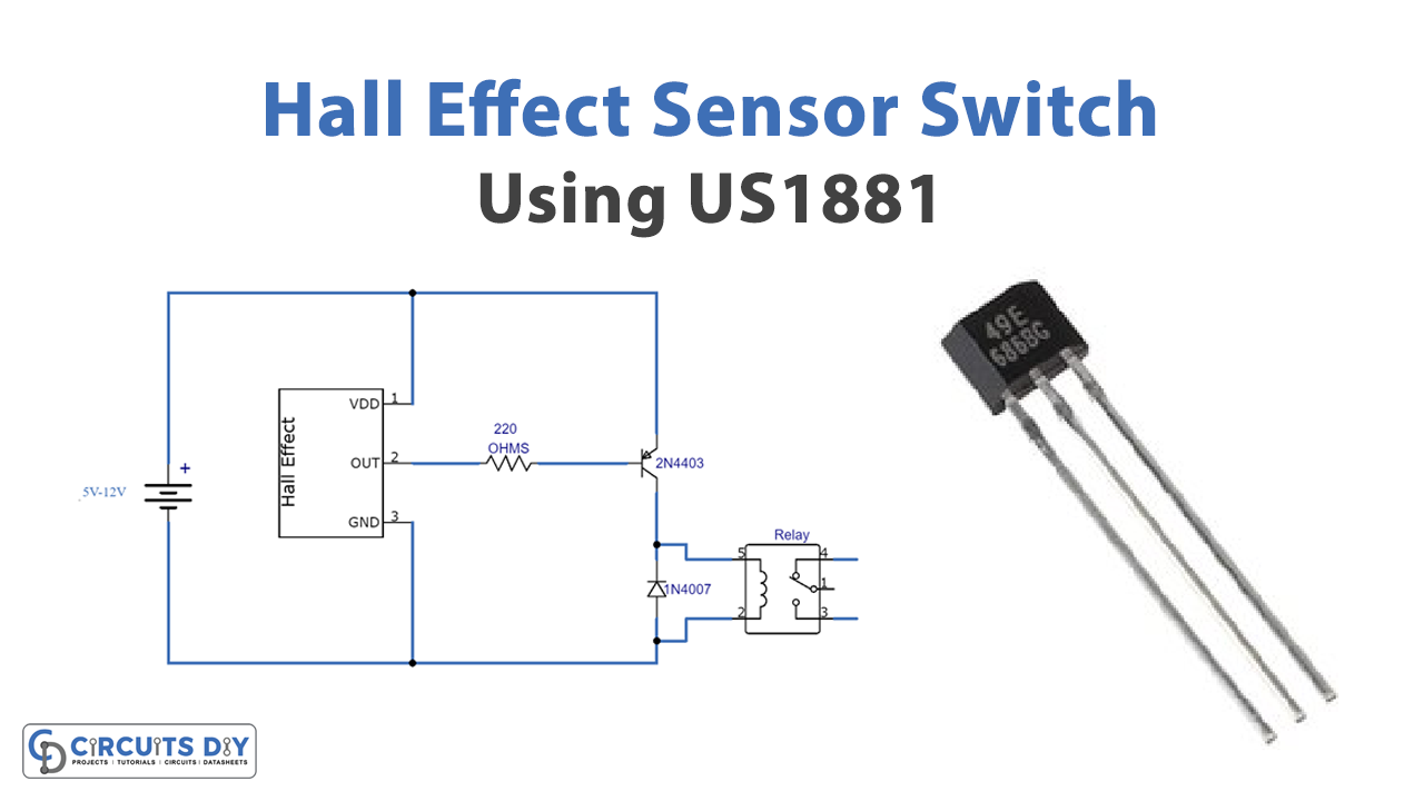
The circuit is quite simple and uses only four components i.e. US 1881 hall effect sensor switch, a relay switch, 220 ohms resistor & a 2N4403 transistor. They don’t cost much and perform the task efficiently.
Hardware Components
The following components are required to make Hall Effect Sensor Circuit
| S.no | Component | Value | Qty |
|---|---|---|---|
| 1. | Input Supply DC | 5-12V | 1 |
| 2. | Hall effect Sensor | US1881 | 1 |
| 3. | Transistor | 2N4403 | 1 |
| 4. | Relay | – | 1 |
| 5. | Diode | 1N4007 | 1 |
| 6. | Resistor | 220Ω | 1 |
US1881 Pinout
For a detailed description of pinout, dimension features, and specifications download the datasheet of US1881
2N4403 Pinout
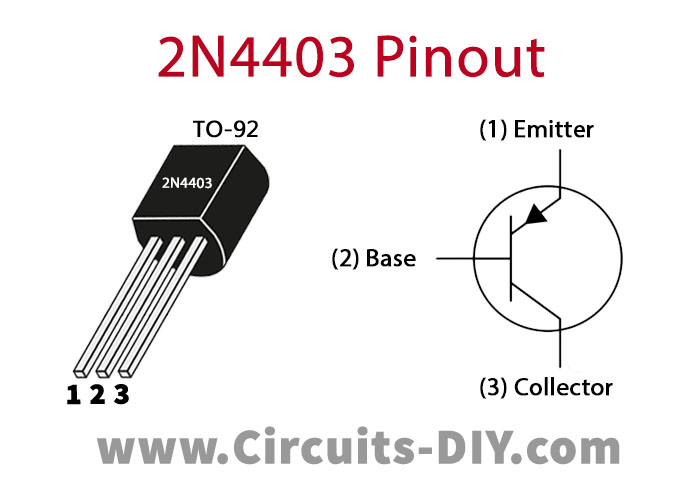
For a detailed description of pinout, dimension features, and specifications download the datasheet of 2N4403
Hall Effect Sensor Circuit

Working Explanation
It is working on the basis of the hall sensor used in this circuit. When it senses or detects a magnetic field then the output of this magnet becomes proportional to the magnetic field and the PNP transistor 2N4403 will activate so will the relay switch. Any AC or DC appliance can be connected with the relay switch and will operate with this circuit. This circuit is operated at 5 to 12V DC, make sure that the relay’s voltage and supply voltage should be the same for this circuit to be working.
Applications and Uses
- Magnetic field detection
- Switching applications, etc.