You all must be familiar with the famous wire loop game. It’s fun to play with and you can even make it yourself with the help of this tutorial. This is a tutorial of a wire loop game circuit, it consists of a wire loop and a shaped wire. This game’s method of playing is simple you just have to move the loop from start to end of the shaped wire making sure to handle the loop properly so it won’t touch the shaped wire. If the loop touches the shaped wire, a sound or light is produced indicating that the game is over now and you lose.
Hardware Components
The following components are required to make Wire Loop Game Circuit
| S.no | Component | Value | Qty |
|---|---|---|---|
| 1. | Input supply | 5-12V | 1 |
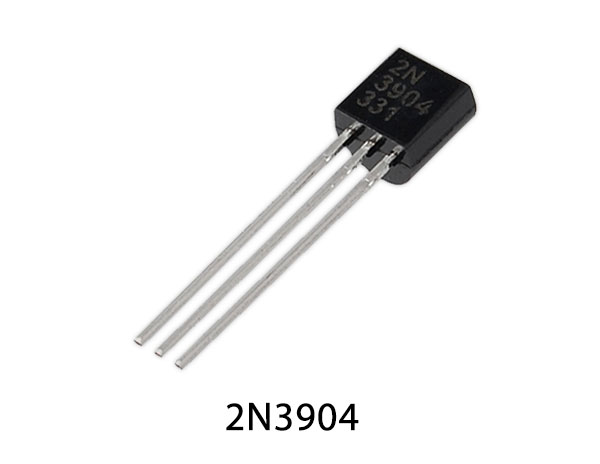
| 2. | Transistor | 2N3906, 2N3904 | 1, 1 |
| 3. | Wires | – | 1 |
| 4. | LED | – | 1 |
| 5. | Piezo buzzer | – | 1 |
| 6. | Resistor | 100KΩ, 470KΩ, 47K, 470Ω, 1KΩ | 1 |
| 7. | Electrolytic Capacitor | 47µF | 1 |
2N3904 Pinout
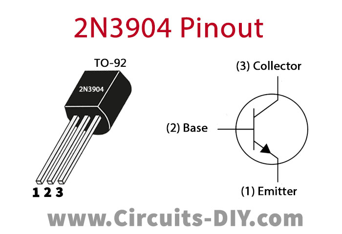
For a detailed description of pinout, dimension features, and specifications download the datasheet of 2N3904
2N3906 Pinout
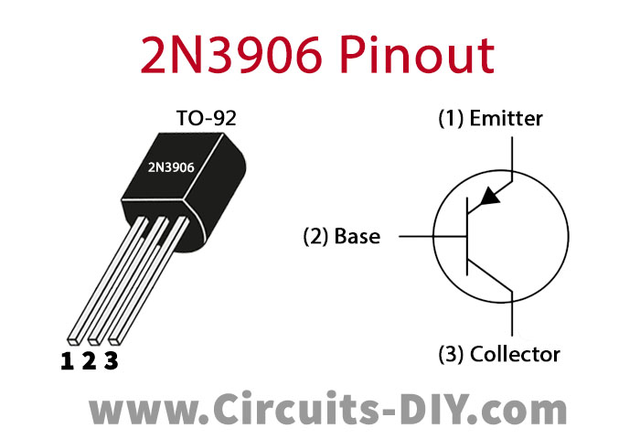
For a detailed description of pinout, dimension features, and specifications download the datasheet of 2N3906
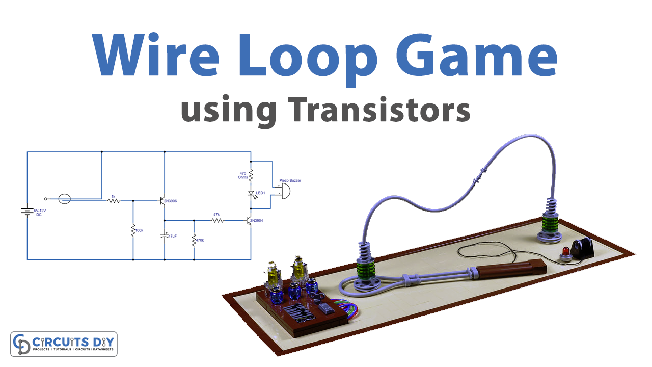
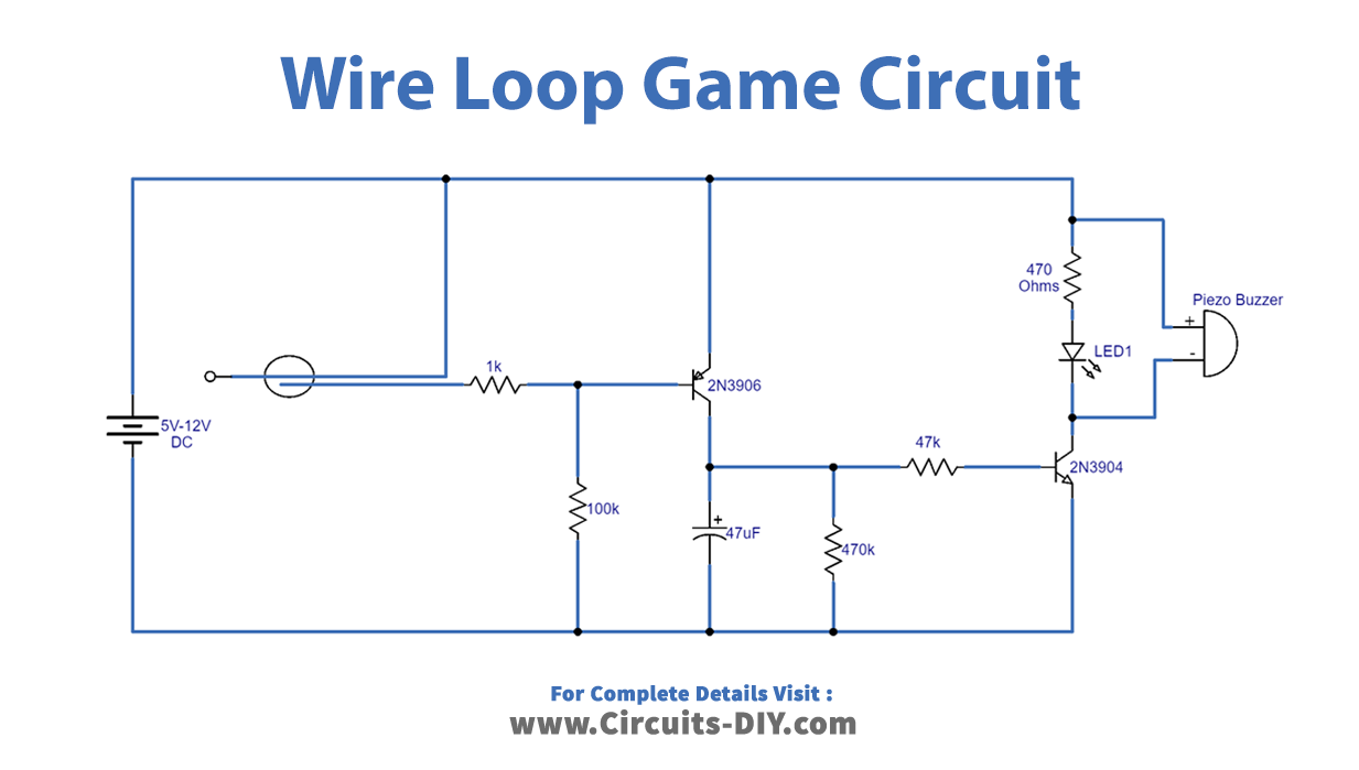
Wire Loop Game Circuit
Working Explanation
The circuit is using two transistors and a few other discrete components. It is operated at 5 to 12 volts. There is a shaped wire and another wire is made into a loop as seen in the circuit diagram, so whenever the loop touches the shaped wire it sends a signal to the transistor 2N3906, it is acting as a switch to the buzzer circuit. There is an LED and a peizo buzzer is connected at the output of this circuit, another transistor is used to amplify the output of the circuit. The buzzer and LED are activated for 5 to 10 seconds when the loop touches the shaped wired. You can also use a relay switch at the output of this circuit instead of a buzzer and connect any AC/DC appliance to operate it with this circuit and make the game more interesting.

