In this tutorial, we are making an interesting project of a movement sensor alarm using a 555 IC. This circuit is also called a detector alarm circuit, it can detect the movement of any object where it is placed. Objects like in your vehicles or those you want to secure or just want to know if anyone is trying to move it.
The circuit is inexpensive and simple as it uses only a few components that are easily available online or in stores. It is built around a 555 timer IC, you must be familiar with this IC because it is used in almost every other electronic circuit. The other thing on which this circuit is based is a pendulum system, it is easily made with wires by making a loop with one wire and attaching a weight with the other wire. Rather than using a buzzer you can use a relay instead and connect any AC/DC appliance with it.

Hardware Components
The following components are required to make Movement Sensor Alarm Circuit
| S.no | Component | Value | Qty |
|---|---|---|---|
| 1. | Input supply DC | 5-15V | 1 |
| 2. | Pendulum system | – | 1 |
| 3. | IC | NE555 Timer | 1 |
| 4. | Buzzer | – | 1 |
| 5. | Resistor | 10K | 1 |
| 6. | Variable resistor | 1MΩ | 1 |
| 7. | Electrolytic Capacitor | 470µF | 1 |
| 8. | Ceramic Capacitor | 0.01uF |
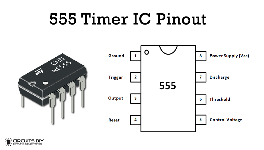
IC NE555 Pinout

For a detailed description of pinout, dimension features, and specifications download the datasheet of 555 Timer
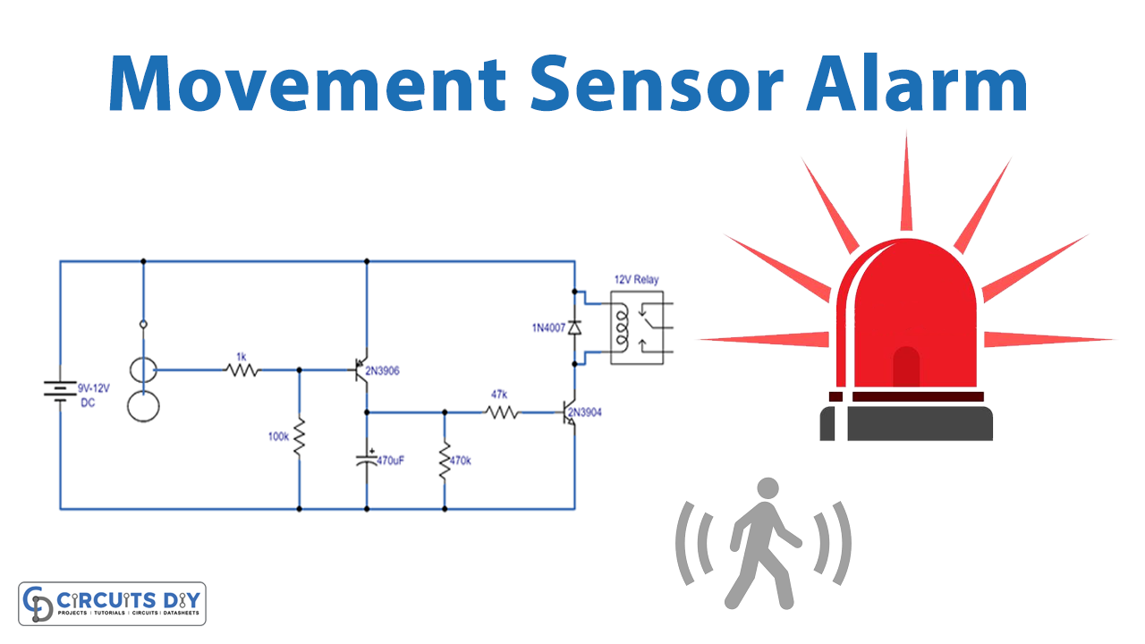
Movement Sensor Alarm Circuit

Working Explanation
The operating voltage of this circuit is 5 to 15 volts DC. On any movement, the pendulum or weight attached to the wire will start moving and touches the loop wire which sends an input signal to the 555 timer IC and it triggers. Now after getting triggered its output goes high for a preset time period and activates the buzzer. The buzzer will be deactivated automatically after the preset time period is over and the 555 timer IC’s output will become low.
The preset time period depends on the 1M variable resistor, which can be changed by changing its value or it can be increased more by using a 1000uF capacitor (or more).


