The water level indicator is one of the famous electronic projects which indicates the level of water in a tank so that a user can refill or stop filling the tank. The water level indicator has so many circuits some of which are really simple consisting of transistors only and some consist of ICs I personally don’t recommend any simple circuit if used for some real purpose application.
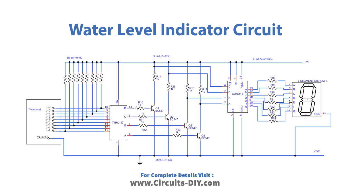
The circuit we are going to discuss is a digital one consisting of 7 segments to display the level of water from (0-9). It is built around priority encoder IC 74HC147, BCD-to-7-segment decoder IC CD4511, 7-segment display LTS543, and a few discrete components. Due to high input impedance, IC 75HC147N senses water in the container from its nine input terminals. The inputs are connected to +5V via 560-
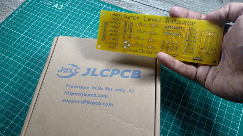
JLCPCB is the foremost PCB prototype & manufacturing company in china, providing us with the best service we have ever experienced regarding (Quality, Price Service & Time).
Hardware Components
The following components are required to make Water Level Indicator Circuit
| S. No | Component | Value | Qty |
|---|---|---|---|
| 1. | PCB | – | 1 |
| 2. | IC | 74HC147, CD4511 | 1 |
| 3. | 7-Segment Display | Cathode | 1 |
| 4. | NPN Transistor | BC547 | 4 |
| 5. | Resistors | 560K, 33K, 12K, 470 ohm | 9, 4, 4, 7 |
| 6. | DC Power Jack | – | 1 |
| 7. | Connecting Wires | – | 1 |
| 8. | Battery | 9v | 1 |
CD4511 Pinout
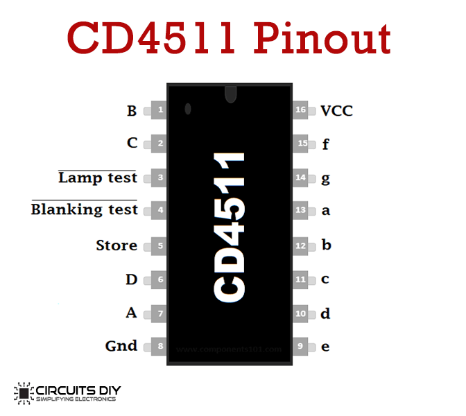
For a detailed description of pinout, dimension features, and specifications download the datasheet of CD4511 IC
Useful Steps
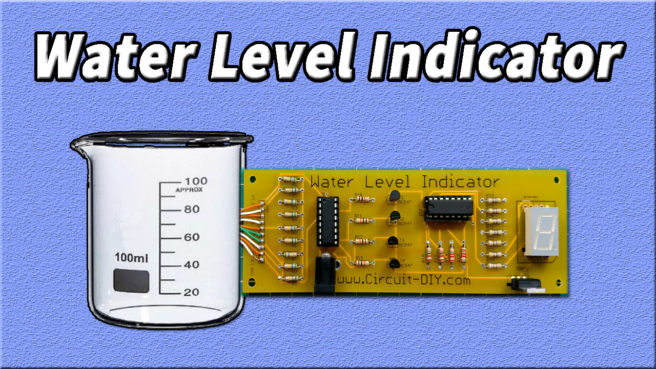
Follow all steps carefully from the video tutorial at the end of this post (Highly Recommended).
- Solder 7 Segment common cathode
- Solder 470 Ohm resistors
- Solder 33k Ohm resistors
- Solder 5v Regulator
- Solder CD5411 IC base
- Solder BC547 Transistors
- Solder 10k Resistors
- Solder 74HC14N IC base
- Solder 560k Resistors
- Solder DC power jack
- Solder wire to all levels (Common, L1, L2, L3, L4, L5, L6, L7, L8, L9)
- Make sure the common signal wire must be at the bottom & L9 at the top of the water level strip
Water Level Indicator Circuit
