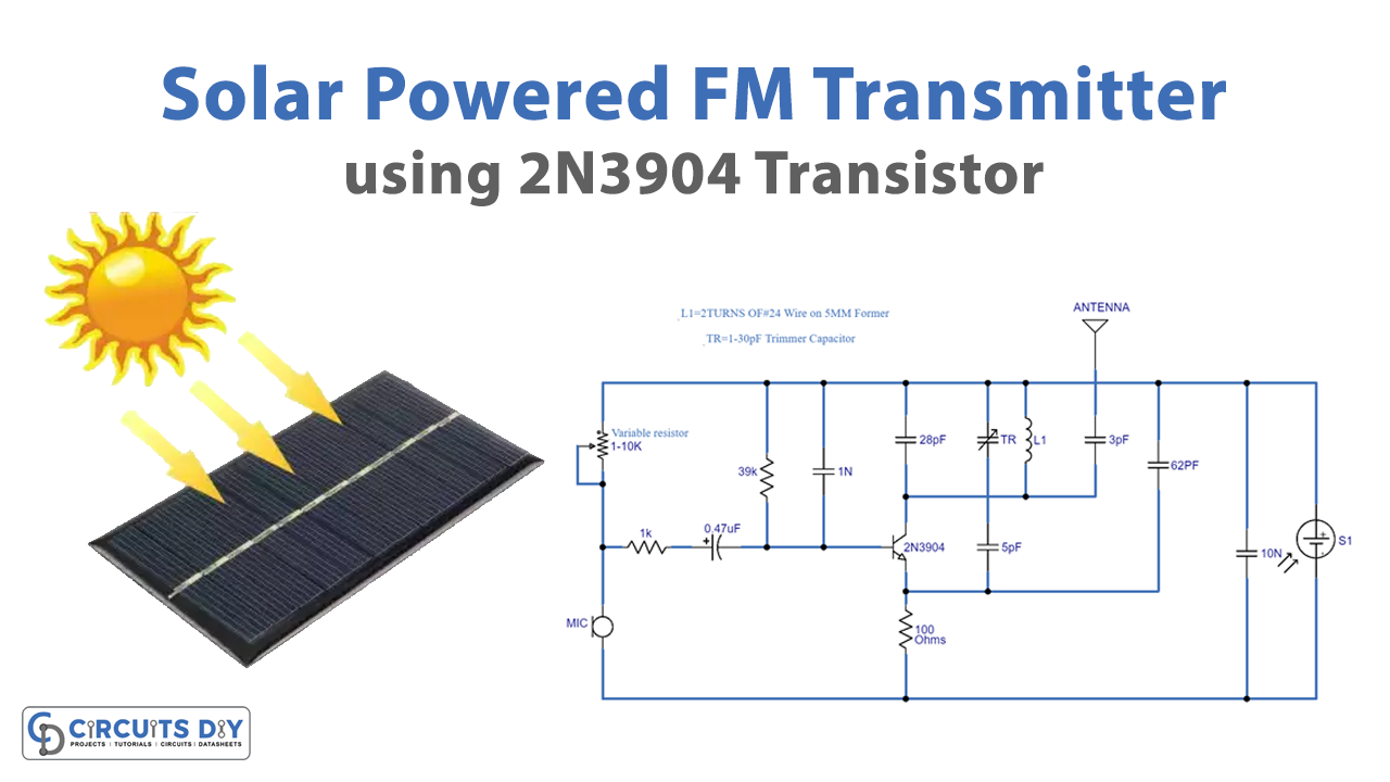
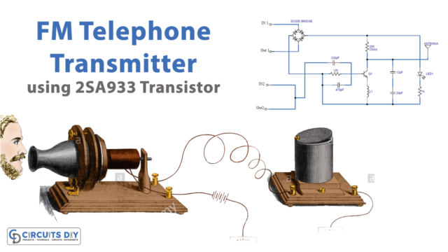
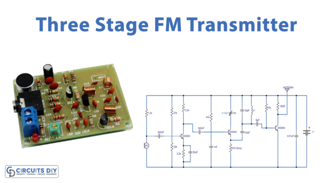
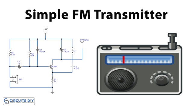
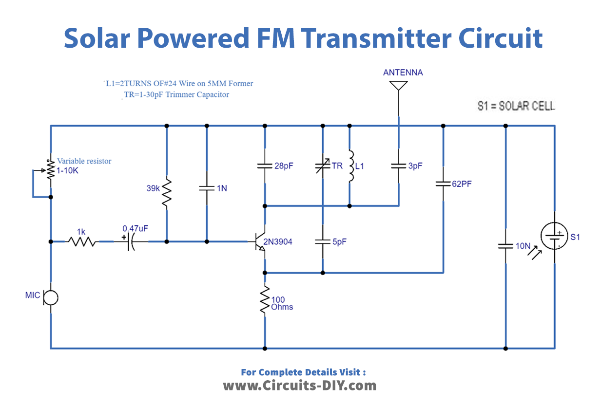
This is a circuit of the “Solar FM transmitter”, the circuit is the same as we examined before in “Best FM Transmitter Topic” however we changed the power source from a 3-volt battery to a solar cell. The circuit will work in direct daylight, utilize tiny solar cells of 3 volt to 5 volts 100mA and try different things with various kinds of solar cells of 3 to 5 volts or above in direct and indirect daylight. For additional insights regarding the circuit please observe the point page “Best FM Transmitter”.
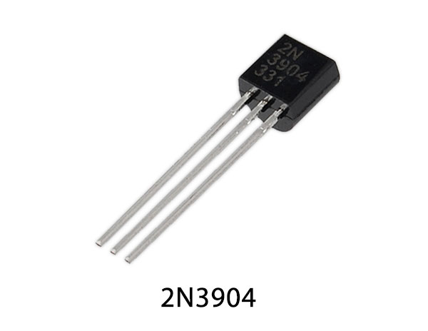
Hardware Component
The following components are required to make Solar Powered FM Transmitter Circuit
| S.no | Component | Value | Qty |
|---|---|---|---|
| 1. | Resistor | 39K, 1K, 100Ω | 1, 1, 1 |
| 2. | Variable Resistor | 1-10K | 1 |
| 3. | Antenna | – | 1 |
| 4. | Coil | 2 turns of #24 wire on 5mm | 1 |
| 5. | Solar Cell | – | 1 |
| 6. | Mic | – | 1 |
| 7. | Transistor | 2N3904 | 1 |
| 8. | Trimmer capacitor | 1-30 pF | 1 |
| 9. | Capacitor | 1nF, 28pF, 5pF, 62pF, 10nF, 0.47µF, 3pF | 1, 1, 1, 1, 1, 1, 1 |
2N3904 Pinout

For a detailed description of pinout, dimension features, and specifications download the datasheet of 2N3904
Solar Powered FM Transmitter Circuit
Working Explanation
In this circuit, we have used the same components as we used in our previous article which was “Best FM transmitter”. In this “Solar FM transmitter Circuit”, we have used some resistors of 39 K, 1K, and 100 Ω, a variable resistor of 1-10 K, capacitors of 1 n, 28 pF, 5 pF, 62 pF, 10 n, 0.47 µF, and 3 pF, a trimmer capacitor of 1-30 pF, a 2N3904 transistor, a Mic and 2turns of #24 wire on 5mm Former, an antenna, and a solar cell. The circuit is intended to take low power from the battery and broadcast a strong signal on the “FM band from 103 MHz to 108 MHz” however you can change frequency width by making a few examinations with the coil. This circuit is very easy to make.
Applications and Uses
These types of low-power FM transmitters are used for playing sound gadgets on
- Television
- Vehicles
- Computer

