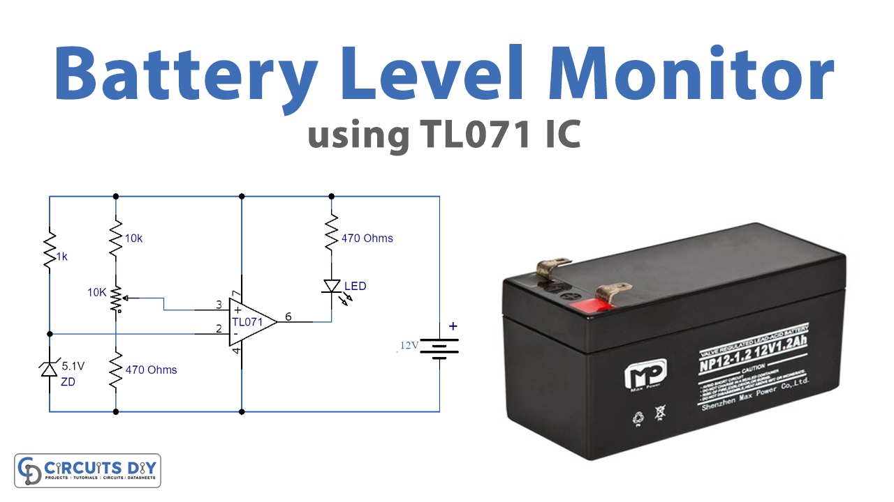
The battery level monitor circuit can be used to indicate the required low battery level. This is an opamp IC 741 low battery alarm indicator circuit that can be used to control a specific low battery voltage The LED will glow and display a visual indication when your battery voltage level reaches the low voltage level preset. You may also attach a tiny buzzer parallel to the LED for the sound signals. The circuit is quick and fast to construct and only requires a few distinct components with the opamp IC.

Hardware Components
The following components are required to make Battery Level Monitor Circuit
| S.no | Component | Value | Qty |
|---|---|---|---|
| 1. | Resistors | 1K, 10K, 470 ohms | 1, 1, 2 |
| 2. | Potentiometer | 10K | 1 |
| 3. | Zener diode | 5.1V | 1 |
| 4. | Battery | 12V | 1 |
| 5. | IC | TL071 | 1 |
| 6. | LED | – | 1 |
TL071 IC Pinout

For a detailed description of pinout, dimension features, and specifications download the datasheet of TL071
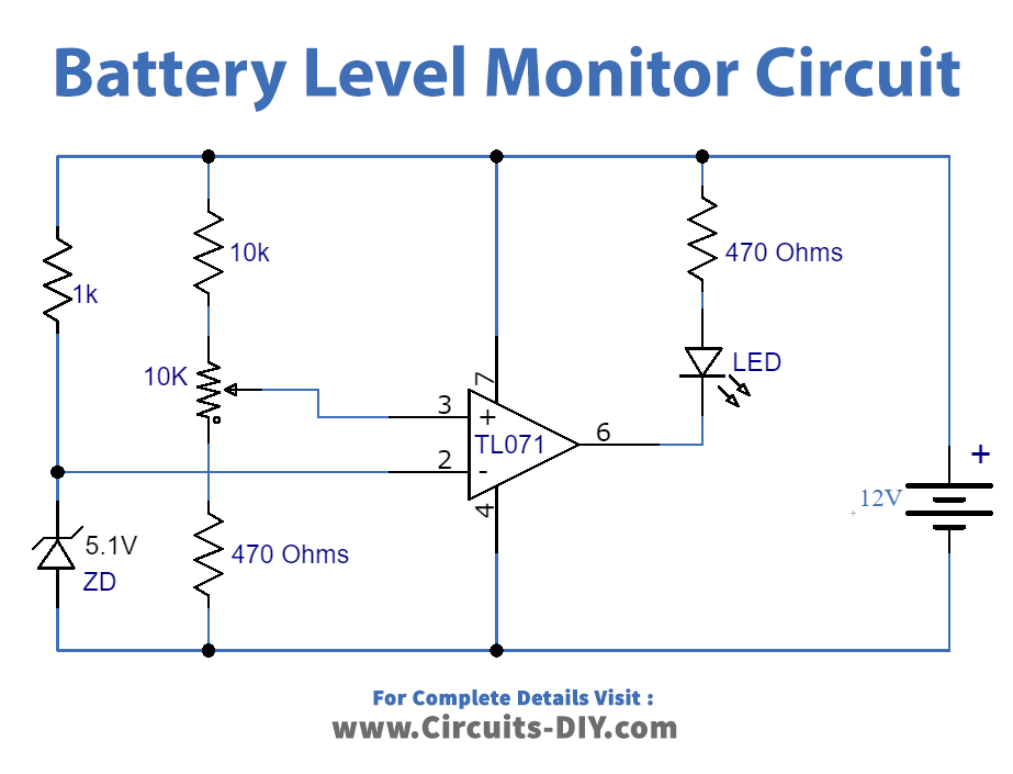
Battery Level Monitor Circuit

Working Explanation
The center of the circuit is a TL071 IC, used herein comparator mode. The 10 K variable resistor is used to set the amount of voltage you want to trigger the LED to. A 5.1V Zener diode is used as the reference voltage. The circuit in question is modified to control 12 Volt batteries. Yet controlling any stress battery can be easily changed. Yet controlling any stress battery can be easily changed. Using a 3.1 V Zener diode in place of 5.1 V Zener for example to control a 6 V battery.
Application and Uses
- The circuit is simple and easy to construct and the opamp IC uses only a few discrete components.
- The circuit may be used to indicate the minimum battery level required.


