A battery bank or power bank is an essential part of your everyday life. Even though they are easily available in the market but electronics hobbyists can make one by themselves. In this tutorial, we are going to show you how to make a DIY Cell Phone, MP3, iPod, or iPad Battery Bank. This can be used as a backup charger for all your devices that require 5V input for charging. It can easily be used anywhere as it’s portable and does not need an electrical outlet.
We have used a 2.8AH SLA battery which will provide enough power in one charge cycle for charging your devices many times. If you want to increase the backup amount then increase the AH of the battery. A 4.5AH battery will provide more backup than a 2.8AH.
Hardware Components
The following components are required to make Battery Bank Circuit
| S.no | Component | Value | Qty |
|---|---|---|---|
| 1. | Step-down Transformer | 110V or 230V AC to 9V/500mA | 1 |
| 2. | Battery | 6V 2.8AH | 1 |
| 3. | Diode | 1N4148, 1N4007 | 2, 5 |
| 4. | Zener diode | 3.6V | 1 |
| 5. | Transistor | 2N4401, 2N4403 | 1, 1 |
| 6. | IC | LM2940CT-5.0 | 1 |
| 7. | Switch | – | 1 |
| 8. | Relay | 9V | 1 |
| 9. | LED | – | 1 |
| 10. | Resistor | 1K, 470Ω | 3, 1 |
| 11. | Electrolytic Capacitor | 470µF/50V, 33µF | 1, 1 |
| 12. | Ceramic Capacitor | 0.1µF | 1 |
| 13. | Variable Resistor | 10K | 1 |
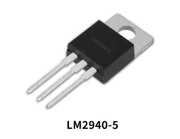
LM2940 Pinout
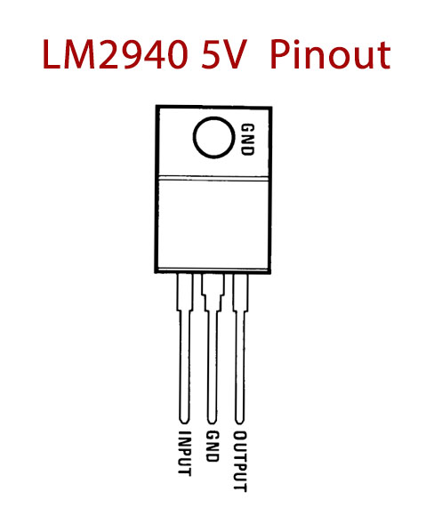
For a detailed description of pinout, dimension features, and specifications download the datasheet of LM2940
2N4403 Pinout
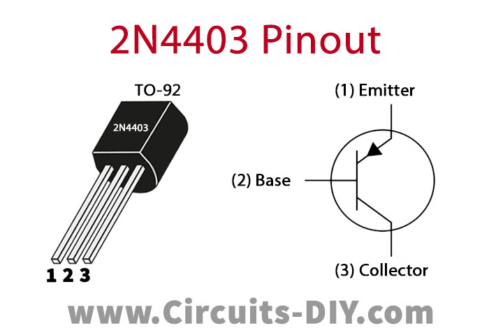
For a detailed description of pinout, dimension features, and specifications download the datasheet of 2N4403
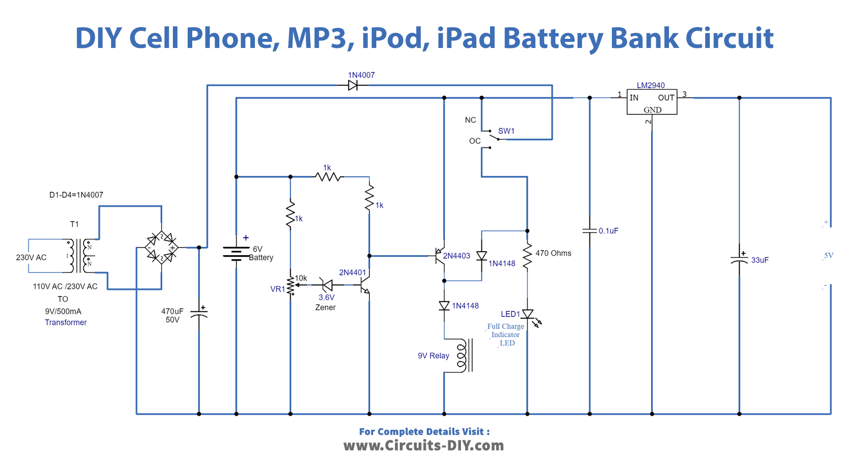
Battery Bank Circuit
Working Explanation
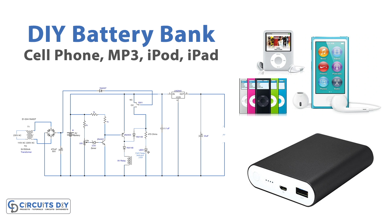
This circuit has three sections. The first section is a power supply which is supplying power to the whole circuit. It consists of a transformer, for stepping down the voltage. A diode bridge for the conversion of AC to DC and a capacitor for filtering. The second section is an automatic battery charger. It is built around two transistors that are responsible for charging the 6V 2.8AH battery.
The third and final section is a voltage regulator part that provides neat and stable 5.0 volts through LM2940CT-5.0 IC and smoothing capacitors. Use a heatsink with this IC to save it from overheating during the process. For the best results fit this circuit into a suitable enclosure.
Circuit Adjustments
The charging port of the circuit requires some adjustments initially.
- Connect the power supply directly with the battery and wait until it reaches 7.2V with the power supply connected. You can use a multimeter for checking the voltage.
- After reaching 7.2V, disconnect the direct connection of the battery with the power supply and connect it as shown in the circuit diagram.
- Now, wait until the meter shows 7.2V then adjust the variable resistor until the Charge indicator (LED) glows.
- Your circuit will be ready to use now.
Applications and Uses
- Cellphones
- iPads
- Media Players
- iPods

