Overview
We have previously released designs utilizing a transistor junction in Zener breakdown mode as a noise source. Those familiar with reverse-biased transistors are aware that the noise voltage amplitude produced this way is highly sensitive to the supply voltage. Additionally, the variation between individual transistors is significant. A straightforward solution is to implement an adjustable supply voltage for the noise generator stage. For instance, a BC547B begins to break down at approximately 8V.
Hardware Components
To make this circuit, you’ll need the following hardware components to get started:
| S.no | Components | Value | Qty |
|---|---|---|---|
| 1 | Transistors | T1 ,T2 = BC547B | 2 |
| 2 | Polar Capacitors | C1 = 100µ 16V C2 = 100n C3 = 10µ 16V C4 = 470n | 1 1 1 1 |
| 3 | Resistors | R1 = 10k R2 ,R3 = 47k | 1 2 |
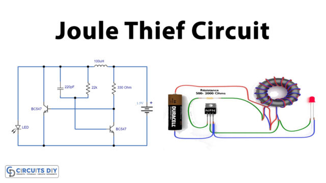
Schematic

By using P1 and R1, you can adjust the voltage across T1 and R2 within the range of 8 to 12V. C3 decouples the reduced supply voltage. To prevent the connected load from influencing the noise source, an impedance buffer made of T2 and R3 is incorporated into the circuit. This buffer is powered directly from the 12V supply. To fine-tune the circuit, connect the output to an oscilloscope and adjust P1 for the highest signal amplitude and optimal noise signal ‘shape.’ The output voltage is around 300mV peak-to-peak (pp), and the circuit’s current consumption is approximately 2mA.