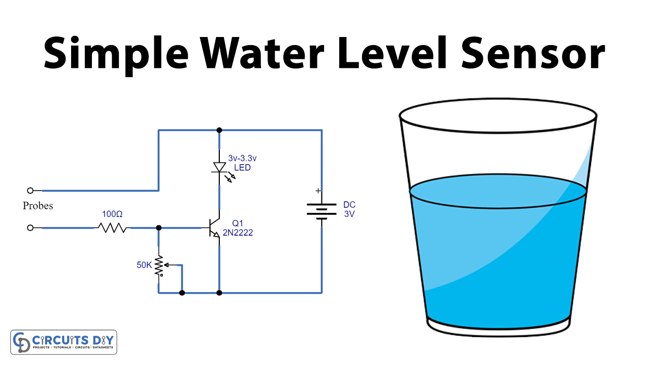
In this tutorial, we are going to make a Simple Water Level Sensor Or Liquid Level Detector circuit. This circuit measures or detects a required level of water, liquid, or any fluid. The circuit diagram is quite simple with only a few components but it can perform a great number of tasks as a monitor for the desired level of any fluid. The LED will be activated when the liquid is detected through probes.
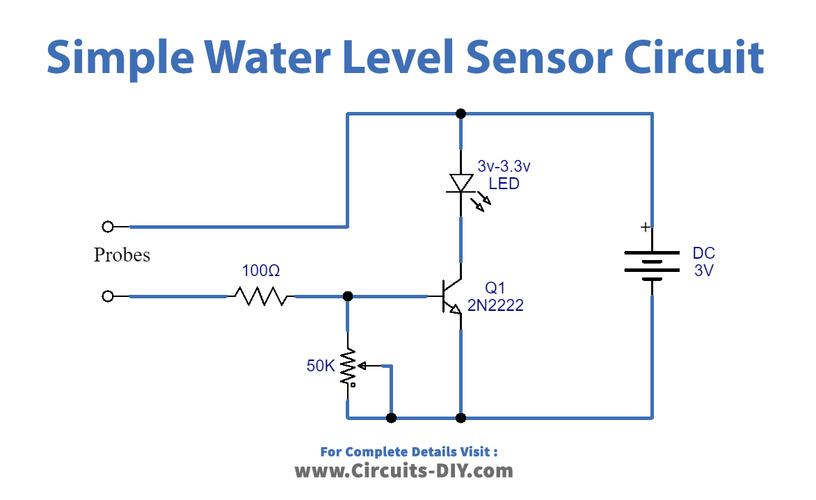
This circuit is using only four components. Probes are used to detect the water. LED is used to provide a visual indication of the required level detection. The transistor used in this circuit is acting as a switch. This circuit is easy and user-friendly and can be made in a few minutes if all the parts are available to you.
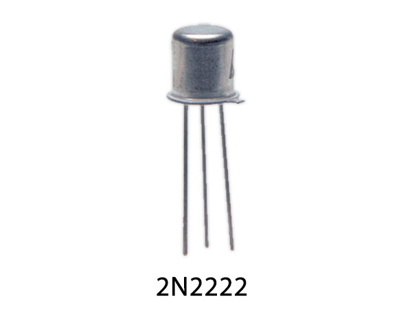
Hardware Components
For a detailed description of pinout, dimension features, and specifications download the datasheet for Water Level Sensor Circuit
| S.no | Component | Value | Quantity |
|---|---|---|---|
| 1. | Battery | 3V | 1 |
| 2. | Probes | – | 2 |
| 3. | LED | 3V-3.6V | 1 |
| 4. | Transistor | 2N2222 | 1 |
| 5. | Variable Resistor | 50K | 1 |
| 6. | Resistor | 100Ω | 1 |
2N2222 Pinout
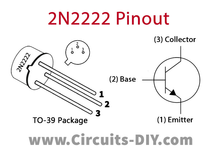
For a detailed description of pinout, dimension features, and specifications download the datasheet of 2N2222
Water Level Sensor Circuit
Working Explanation
The operating voltage of this circuit is 3 volts. When the required water level (or any other liquid) is detected through the probes it will activate the transistor. This will turn on the LED giving a visual indication of the water level detection. A 50K ohms variable resistor is used to adjust the sensitivity of this circuit. Since the input voltage of this circuit is 3V you should use an LED of the same voltage. This circuit can be operated by two batteries of 1.5V of any size
Applications and Uses
It can be used to measure and detect the required water, fluid, or liquid in a
- Tank
- Pool
- Well
- Aquarium
- Washing Machine

