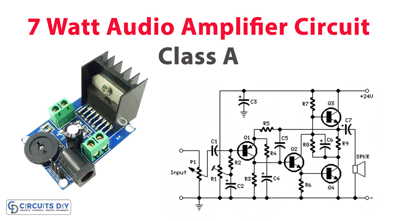
More than several years have passed since this website first published the 3 – 5W Class-A Audio Amplifier, and its success has only grown over time. Recently, some minor adjustments were made to enhance its performance. These changes included adding components like R1, Q2, R6, and substituting Q4 with a Darlington transistor, resulting in a significant improvement in output.
The modifications led to several notable improvements. The open-loop gain saw an increase, and distortion levels at various power outputs were drastically reduced (for example, by up to 30 times at 500mW). Current consumption dropped to under 500mA, while the maximum output power surged to 7.2W RMS into an 8 Ohm load. Additionally, the input sensitivity was set at around 250mV RMS, allowing direct connection of devices like a CD player or Tuner without requiring a preamplifier.
The lower power consumption enabled the use of a straightforward yet highly effective regulated power supply, utilizing the LM317 IC. This power supply, even with a modest heatsink, can efficiently drive two amplifiers. It’s crucial to set the amplifier’s power supply voltage precisely to 24V using Trimmer R2, as depicted in the Power Supply Circuit diagram below.
Within the amplifier itself, Trimmer R1 was introduced to optimize the output power to its maximum capacity (7.2W RMS). This component ensures that the voltage at the positive lead of C6 is precisely half of the supply voltage, i.e., 12V (with P1 fully turned anticlockwise).
Hardware Components
You’ll need the following hardware components to get started:
| S.no | Components | Value | Qty |
|---|---|---|---|
| 1 | Transistors | Q1=BC560C-45V/100mA PNP Q2=BC337-45V/800mA NPN Q3=BD437-45V/4A NPN Q4=BD675A -45V/4A NPN | 1 1 1 1 |
| 2 | Polar Capacitors | C2=47µF-25v C3,C6=470µF-25v C4=220µF-25v C7=1000µF-25v C1=470nF-63v C5=47pF-63v | 1 2 1 1 1 1 |
| 3 | Resistors | R1=100k-1/2w R2=100k-1/4w R3=8k2-1/4w R4,R8=100R-1/4w R5=2k7-1/4w R6=1k-1/4w R7=680R-1/4w R9=1R-1/2w | 1 1 1 2 1 1 1 1 |
| 4 | Potentiometer | P1=50K Log Potentiometer (or 47K) | 1 |
| 5 | Speakers | SPKR=One or more speakers wired in series or in parallel Total resulting impedance: 8 Ohm Minimum power handling: 10W | 1 |
Schematic

24VDC Power Supply Circuit
The regulated power supply circuit is designed to be user-friendly and efficient. The suggested values for the parts are specifically tailored to power a stereo version of this audio amplifier design.
Notes:
- With both amplifiers connected to the regulated power supply, adjust Trimmer R1 to obtain exactly 24V at the output pin of IC1.
- Adjust R1 in each amplifier to obtain exactly 12V across C6 positive lead and negative ground.
- Total current drawing of each amplifier is about 450-500mA and should not require adjustment.
- Each output transistor (Q3 and Q4) must be mounted on a finned heatsink of 120x50x25mm. minimum dimensions.
| S.no | Components | Value | Qty |
|---|---|---|---|
| 1 | Integrated Circuit IC | IC1=LM317 | 1 |
| 2 | Polar Capacitors | C1=4700µF 35v or 50v | 1 |
| 3 | Diode | D1=Diode bridge-100 to 400V,2 to 4A | 1 |
| 4 | Resistors | R1=2K7 1/2w R2=5K 1/2w R3=220R 1/4w | 1 1 1 |
| 5 | LED’s | D2=LED Any type and color | 1 |
| 6 | Switch | SW1=SPST Mains switch | 1 |
| 7 | plug | PL1=Male Mains plug with cord | 1 |
Schematic

Technical data:
- Max output power:545mW RMS into 32 Ohms (1KHz sine wave)
- Input sensitivity:250mV RMS for 30mW output, 1V RMS for full output
- Frequency response @ 100mW RMS:Flat from 20Hz to 20KHz
- Total Harmonic Distortion @ 1KHz and 10KHz:
- 0.5mW 0.005% 1mW 0.004% 15mW 0.002% 100mW 0.002% 136mW 0.0045%
- 250mW 0.013% 500mW 0.04%