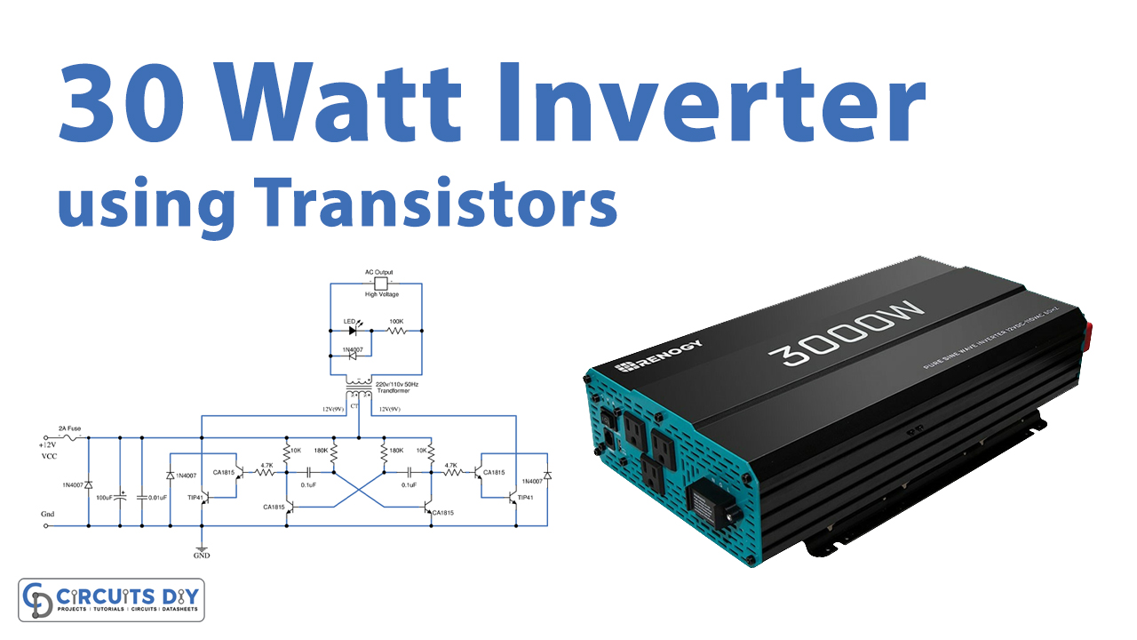
In this tutorial, we are going to make a “Simple 30-watt Inverter circuit using 6 transistors”.
A power inverter is a power electronic device or circuitry that changes direct current (DC) to alternating current (AC). Let’s say you are the owner of a car, boat, or another vehicle with enough free space and want to be able to watch TV cook, power a laptop onboard, or want to spend some time in the mountains. you’ll be needing a power inverter. They are devices that turn your vehicle battery’s direct current (DC) into alternating current (AC). It increases the DC voltage and changes it to AC, then uses it to power your devices. This is a simple inverter circuit of 30 watts, It converts DC voltage from a 12V battery to AC 220V-230V at 50Hz which is the same electricity used in your house.
Hardware Components
The following components are required to make 30 Watt Inverter Circuit
| S.no | Component | Value | Qty |
|---|---|---|---|
| 1 | Transistors | C1815, TIP41 | 4, 2 |
| 2 | Diode | 1N4007 | 2 |
| 3 | LED | – | 1 |
| 4 | Ceramic Capacitors | 0.1uF, 0.01uF | 2, 1 |
| 5 | Electrolytic Capacitor | 100uF | 1 |
| 6 | Resistor | 10k,180k,4.7k,100k | 2,2,2,1 |
| 7 | Fuse | 1A | 1 |
| 8 | Transformer | – | 1 |
| 9 | PCB | – | 1 |
| 10 | Heat sink | – | – |
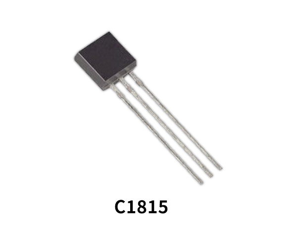
C1815 Pinout
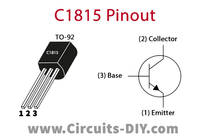
For a detailed description of pinout, dimension features, and specifications download the datasheet of C1815
TIP41 Pinout
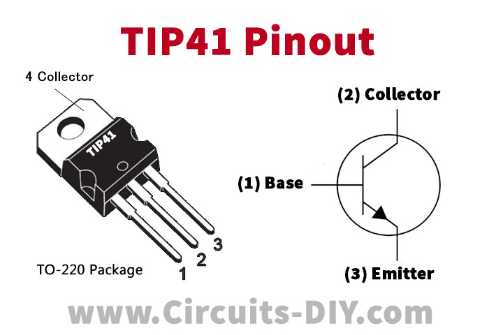
For a detailed description of pinout, dimension features, and specifications download the datasheet of TIP41
30 Watt Inverter Circuit
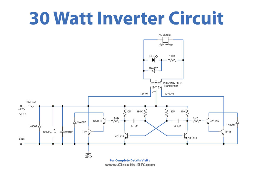
Working Explanations
In this circuit, we need a waveform that has high power with both parts positive and negative. So, we should use a center tap transformer and two amplifier set, that has the same electrical features.
Q3 and Q4 are pre-driver amplifiers, that use many numbers that are NPN type. So, we choose 2SC1815. Q5, Q6 are high output drive amplifier transistors. we selected a 2SD313 because it has a high current collector of more than 1A and is cheap. You can also use H1061 or TIP41 for better quality (high current and voltage). R5, R6 are resistors to provide current to bias the base of Q3, Q5, and Q4, Q6.
when Q1 conducts current, result to Q2 not works. So current flow through R4, R6 provide bias current to Q4, Q6 conducts current. The result has current from the battery to the transformer coil. But when Q1 stops it causes Q2 to work. So current flow through R1, and R5, to provide the current, that triggers Q3, and Q5 to conduct current. Thus, the current from the battery flows through another transformer coil instead. which Causes electricity inductance through the transformer switch between positive and negative with high power. Transformer increases the voltage from 12V AC into 220V AC at frequencies of 50Hz.
D1 and D2 are diodes that protect the working of the transformer from noise. D3 is a protection diode. If D3 is connected in the wrong polarity. The negative voltage will flow through D3 instead. Makes the circuit safe. But D3 may be short and F1-fuse blown instead. F1 is fuse protect overcurrent 1A and in case of the wrong polarity, F1 is also blown. LED1 is power on display when having the power 220V 50Hz completely. The R7 acts to reduce current to LED1. And there is D4 set the polarity to LED1 appropriately.
Applications
This circuit can be used in cars and other vehicles to charge small batteries. It can power 2-3 Air pumps and other simple appliances.


