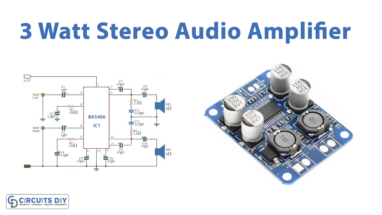
In this tutorial, we are going to make an “Amplifier Stereo 3W based on power IC BA5406”.
BA5406 stereo amplifier is a monolithic integrated circuit. As BA5406 is a dual OTL power amplifier, it includes two sets of high-power AF Amplifiers inside and can deliver 3W per channel into an 8-ohm loudspeaker at a 12V supply. It does not require an output coupling transformer and can be operated from a single supply. The operating voltage range is from 9 to 12V DC.
The BA5406 has low noise, low thermal resistance ( makes heat-sink design easy ), great channel separation, good channel isolation, small pop-up noise, Immunity to supply voltage drop, and is available in a 12-pin SIP package for mounting easy and saving space on a PCB. . All these features make the IC suitable for low-power applications.

Hardware Components
The following components are required to make Stereo Amplifier Circuit
| S.no | Component | Value | Qty |
|---|---|---|---|
| 1. | Amplifier Stereo IC | BA5406 | 1 |
| 2. | Capacitor | 1uF 50V, 3.3uF 50V, 47uF 25V, 470uF 25V | 2, 2, 4, 2 |
| 3. | Polyester capacitor | 0.22uF 63V | 2 |
| 4. | Resistor | 100 ohms, 2.2 ohms | 2, 2 |
| 5. | Speaker | 8 ohms | 2 |
| 6. | Power supply | 12V | 1 |
BA5406 Pinout
For a detailed description of pinout, dimension features, and specifications download the datasheet of BA5406
Stereo Amplifier Circuit
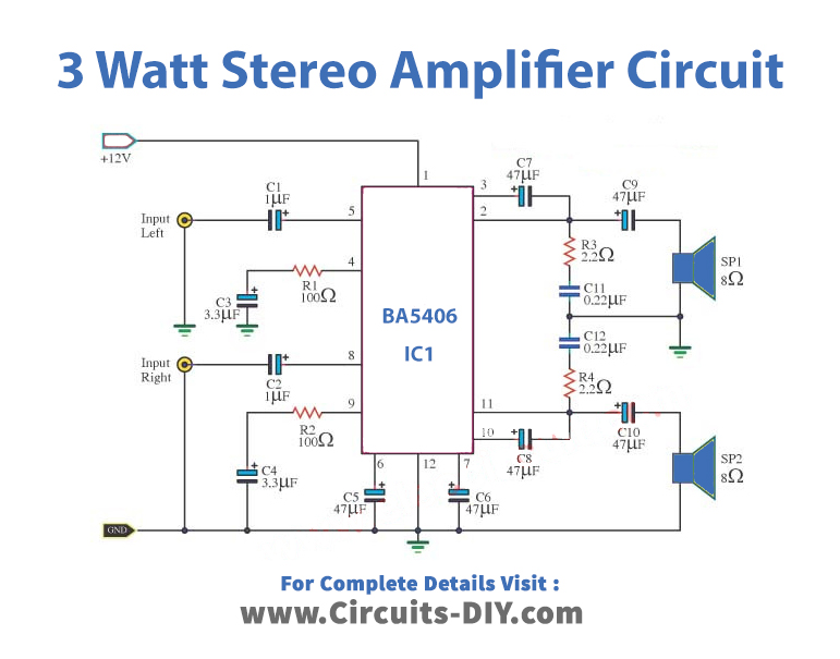
Working Explanation
As shown in the circuit diagram, BA5406 is circuited to deliver 3×2 watts into 8-ohm loudspeakers at a supply voltage of 12 volts. First, we apply the 12V power supply to this circuit. Quiescent current 20-70mA, typically 40mA. Then, we enter both the input signals right and left which are connected to pin 5 and pin 8 of BA5406 through the C1 and C2 to coupling signal, which prevents DC interference. Both input signals go out of pin 2 and pin 11 of IC. We configure this IC as a NON-inverting Amplifier. It does not change the phase of signals.
Two pins of IC pin 3 and pin 10 connected with the C7 and C8, respectively. Both are Bootstrap helped in better gain. C5 and C6 are connected to pin 6 and pin 7. They are used to filter noise from the IC. C11 and R3 form a Zobel network for the left output while C12 & R4 form the same for the right channel. The purpose of the Zobel network is to reduce oscillations and improve the high-frequency stability of the amplifier.
Then these output signals further go through C9 and C10, which couples the output to both the 8-ohm speakers.
Applications
This circuit is best suitable for expanding the use of music in a private room. Or used in any experiment.
Due to low RF radiation, so suited for stereo radio cassette recorders.


