Introduction
In many electronic circuits, we need a single frequency through a band of frequencies. Because different circuit requires a different particular range of frequencies. For example, some circuit cannot afford higher frequencies, while some doesn’t need lower ones, and some require a wider range of frequencies. So to filter out the frequencies, we use passive circuits which we are going to discuss in this article. So, in this tutorial, we are going to the “Passive Filter Circuit”
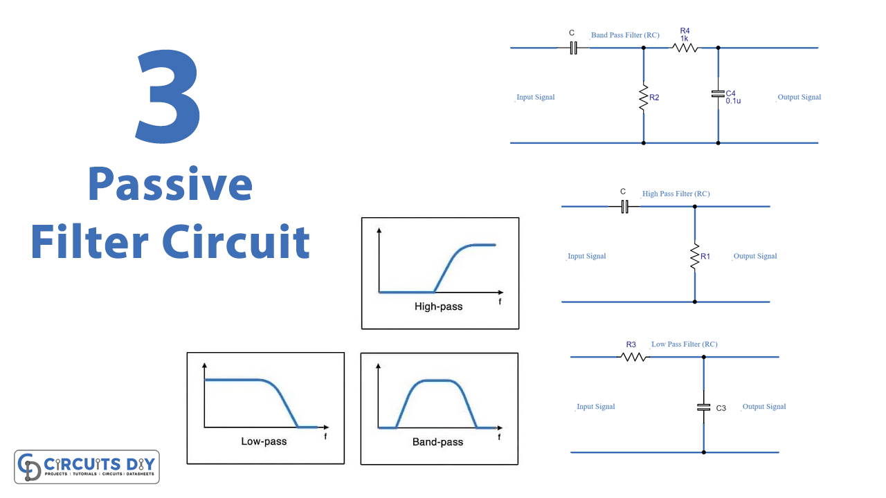
Passive filters are called passive filters because we created them through passive elements like capacitors, and resistors. These passive filters have three different types.
- Passive low-pass filter.
- High-pass passive filter
- Passive band-pass filter.
Passive Low-Pass Filter
The low pass filter is obtained by connecting a resistor in series with the capacitor, where output is taken across the capacitor. This removes higher frequencies while allowing the lower frequencies to pass through them.
Passive High-Pass Filter
The high pass filter is obtained by connecting a capacitor in series with the resistor, where output is taken across the resistor. This removes lower frequencies while allowing the higher frequencies to pass through them.
Passive Band-Pass Filter
The band-pass channel is acquired by cascading passive low-pass and passive high-pass filters. This cascading will give a specific filter that passes just specific frequencies. This passive filter can pass either a wide range of frequencies or narrow frequencies.
Hardware Required
Circuit Diagrams
Low-Pass Filter

High-Pass Filter

Band-Pass Filter

Working Explanation
The first circuit, which is the low-pass passive filter allows frequencies that are lower than the cut-off frequency, while you can calculate the cut-off frequency as Fc = 1/(2πRC). You can change the cut-off frequency by changing the values of the resistor and capacitor.
The second circuit, which is the high-pass passive filter allows frequencies that are above the cut-off frequency, while you can calculate the cut-off frequency as Fc = 1/(2πRC). You can change the cut-off frequency by changing the values of the resistor and capacitor.
The third circuit, which is the band-pass filter is a combination of the first two circuits. By creating a set of RC elements in series and connecting another set of RC elements in parallel the circuit operates as a band-pass filter.
Application and Uses
- We can use a low-pass passive filter in different circuits to filter the noise. Thus, can be used in audio amplifiers to reduce high-frequency noise.
- We can use a high-pass filter for the amplification of sound.
- The band-pass filters can be used to optimize signal-to-noise ratio, in optical communication, etc.