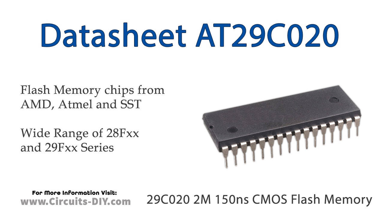
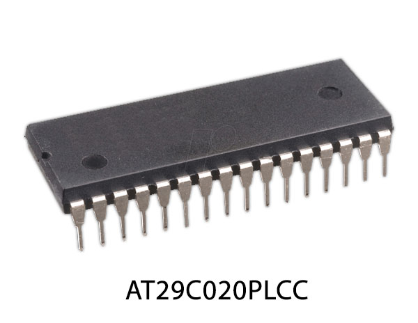
The 29C020 is a 5-volt-only in-system Flash programmable and erasable read-only memory (PEROM). Its 2 megabits of memory are organized as 262,144 bytes. The device offers access times to 90 ns with power dissipation of just 220 mW over the commercial temperature range. When the device is deselected, the CMOS standby current is less than 100 µA. Device endurance is such that any sector can typically be written to in excess of 10,000 times.
To allow for simple in-system re-programmability, the AT29C020 does not require high input voltages for programming. Five-volt-only commands determine the operation of the device. Reading data out of the device is similar to reading from an EPROM. Reprogramming the AT29C020 is performed on a sector basis; 256-bytes of data are loaded into the device and then simultaneously programmed
29C020 Pinout
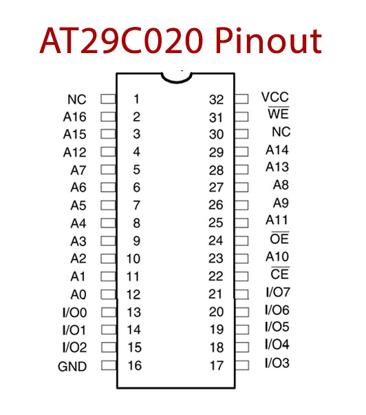
29C020 Pin Configuration
| Pin No | Pin Name | Description |
|---|---|---|
| 1 | NC | Not Connect |
| 2 | A16 | Address Pin 16 |
| 3 | A15 | Address Pin 15 |
| 4 | A12 | Address Pin 12 |
| 5 | A7 | Address Pin 7 |
| 6 | A6 | Address Pin 6 |
| 7 | A5 | Address Pin 5 |
| 8 | A4 | Address Pin 4 |
| 9 | A3 | Address Pin 3 |
| 10 | A2 | Address Pin 2 |
| 11 | A1 | Address Pin 1 |
| 12 | A0 | Address Pin 0 |
| 13 | I/O 0 | Data Inputs/Outputs 0 |
| 14 | I/O 1 | Data Inputs/Outputs 1 |
| 15 | I/O 2 | Data Inputs/Outputs 2 |
| 16 | GND | Ground Pin |
| 17 | I/O 3 | Data Inputs/Outputs 3 |
| 18 | I/O 4 | Data Inputs/Outputs 4 |
| 19 | I/O 5 | Data Inputs/Outputs 5 |
| 20 | I/O 6 | Data Inputs/Outputs 6 |
| 21 | I/O 7 | Data Inputs/Outputs 7 |
| 22 | CE’ | Chip Enable Pin |
| 23 | A10 | Address Pin 10 |
| 24 | OE’ | Output Enable Pin |
| 25 | A11 | Address Pin 11 |
| 26 | A9 | Address Pin 9 |
| 27 | A8 | Address Pin 8 |
| 28 | A13 | Address Pin 13 |
| 29 | A14 | Address Pin 14 |
| 30 | NC | No Connection |
| 31 | WE’ | Write Enable Pin |
| 32 | VCC | Power Supply |
29C020 Key Feature
- Fast Read Access Time – 90 ns
- 5-Volt-Only Reprogramming
- Sector Program Operation
- Single Cycle Reprogram (Erase and Program)
- 1024 Sectors (256 bytes/sector)
- Internal Address and Data Latches for 256-Bytes
- Internal Program Control and Timer
- Hardware and Software Data Protection
- Two 16 KB Boot Blocks with Lockout
- Fast Sector Program Cycle Time – 10 ms
- DATA Polling for End of Program Detection
- Low Power Dissipation
- 40 mA Active Current
- 100 µA CMOS Standby Current
- Typical Endurance > 10,000 Cycles
- Single 5V ± 10% Supply
- CMOS and TTL Compatible Inputs and Outputs
You can download this datasheet for 29C020 2M 150ns CMOS Flash Memory – Datasheet from the link given below:


