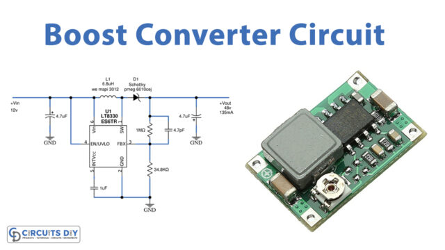
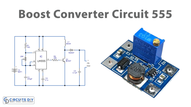
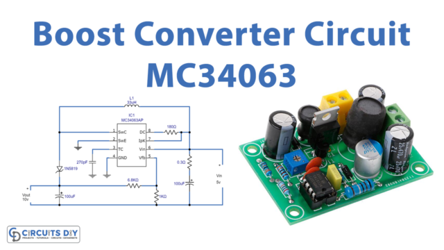
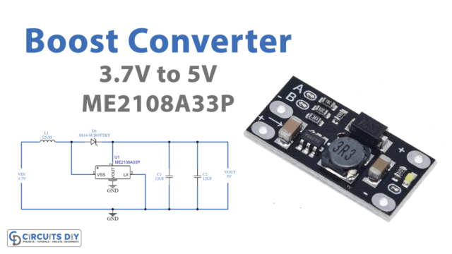
Most of the time, we need slightly higher voltage than our power supplies can provide (one common situation is, we need 12V but our battery can only provide 9V). Here the question comes to mind, is there a way to convert one DC voltage to another? Or more specifically, is there a way to step up the level of voltage that we already have without going through the labor of very intricate circuits? So a simple solution for this situation is a boost converter. A boost converter also known as a step-up converter is one of the simplest types of switch-mode converter.
As the name suggests, the converter takes an input voltage and boosts it. In other words, it’s like a step-up transformer i.e it steps up the level of DC voltage from low to high while decreasing the current from high to low and the supplied power is the same. Here this circuit is used to convert 2.7 volts to 5 volts by using LTC3440, it is a high-efficiency fixed-frequency Buck-Boost DC/DC converter.
Hardware Required
| S.no | Component | Value | Qty |
|---|---|---|---|
| 1. | IC | LTC3440 | 1 |
| 2. | Schottky Diode | MBRM120T3 | 1 |
| 3. | Inductor | 10µH | 1 |
| 4. | Capacitor | 10µF/16v, 22µF, 0.1µF, 1.5nF | Each One |
| 5. | Resistor | 1MΩ, 60.4KΩ, 15KΩ, 619KΩ, 200KΩ | Each One |
| 6. | On/off Switch | – | 1 |
| 7. | Connecting Wires | – | – |
Circuit Diagram

Working Explanation
As we can see in the circuit, the main part is an LTC3440 IC. This IC is a highly efficient DC-to-DC converter that can be operated from input voltages below, above, or equal to the output voltage. In terms of synchronous rectification, LTC3440 provides up to 96% efficiency, and up to 600mA of output current is guaranteed. The IC has a built-in synchronizable oscillator whose frequency can be adjusted from 300 kHz to 2 MHz. In this circuit LTC3440 is wired as a 5V boost converter capable of delivering a steady 5V output @ 300mA from an input voltage of 2.7 to 4.2 V. Here resistor R4 is used to set the oscillator frequency, while resistors R1 and R2 are used to set the output to 5 volts. And resistor R3 and capacitor C1 form a frequency compensation network, while C3 serves as the input bypass capacitor. S1 is the shutdown switch and C2 is the output filter capacitor. And make sure that diode D1 must be placed as close to the IC as possible on the PCB.
Applications
- Automotive applications
- Power amplifier applications
- Adaptive control applications


