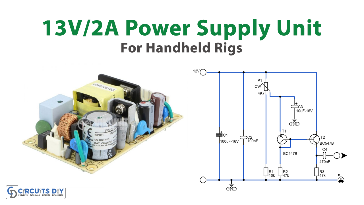
Overview
This compact 13V/2A power supply, ideal for ham radio rigs and other VHF/UHF portable PMRs, utilizes the STR2012/13 voltage regulator IC from Sanken Electric Co. Many power supplies for handheld amateur radio rigs often rely on the LM317, LM350, or the classic LM723. However, these regulators typically require a significant number of external components, and factors such as total power dissipation and input voltage range must also be considered. The STR, a hybrid power IC, incorporates a switch-mode power supply, providing a fixed output voltage and accommodating relatively high input voltages.
An additional benefit of the STR is its relatively high power dissipation rating. The 5-pin STR IC is available for output voltages of 5.1V, 12V, 13V, 15V, and 24V, all rated for a 2A output current. In this application, the STR2012 and STR2013 are recommended for output voltages of 12V and 13V, respectively. Since most handhelds operate at voltages between 12.6V and 13.8V, the STR2013 is typically the preferred choice. To protect the radio from overvoltage, a high-speed crowbar circuit is added to the regulator output. Thyristor Th1 (a TIC106 or 2N4442) is triggered if the output voltage exceeds the zener voltage of D2, which is approximately 15V. When activated, the thyristor short-circuits the supply output, safeguarding the radio and blowing fuse F1.
Hardware Components
To make Handheld Rigs, you’ll need the following hardware components to get started:
| S.no | Components | Value | Qty |
|---|---|---|---|
| 1 | Integrated Circuit IC | IC1 = STR2012 or STR2013 | 1 |
| 2 | Transistors | TIC106 2N4442 | 1 1 |
| 3 | Capacitors | C1 = 1000µ 63V C2 = 1000µ 25V | 1 1 |
| 4 | Diodes | D1 = 1N5401 D2 = 15v 400mW | 1 1 |
| 5 | Resistors | R1 = 1k5 | 1 |
Schematic

Diode D1 provides reverse polarity protection in conjunction with fuse F1. To manage the heat dissipation, the STR regulator should be mounted on a heatsink. The power supply efficiency is around 80%, with a ripple rejection of approximately 45 dB. The input voltage to the regulator should range between 18 and 35V. For the coil (L1), the 1430430 model from New-port is recommended. If this is unavailable, a triac suppressor type coil can be used as an alternative.
However, keep in mind that these coils typically have an inductance of only 100µH. To achieve the desired inductance of around 300µH, you’ll need to calculate the number of turns and add an additional 70% to the original count. Lastly, ensure the wire between pin 3 of the STR and ground is kept as short as possible. Additionally, connect the negative terminals of C1 and C3 at this point to form a ‘star’ ground connection.