Introduction
In small electronic projects that need an AC supply, the conversion of DC into an AC supply is a big deal. Even in big projects designers need to convert the DC voltages. For example, we all are conscious of electrical load shedding. Hence, have used or seen the UPS systems. And, if you are familiar with the UPS, then you must have seen the battery of this UPS. Certainly, this battery is a DC battery. However, the appliances we use in our homes are AC appliances. In the same vein, Solar backup systems, and conditioning systems also require AC voltages. Therefore, an inverter is required to convert the DC voltage into an AC voltage.
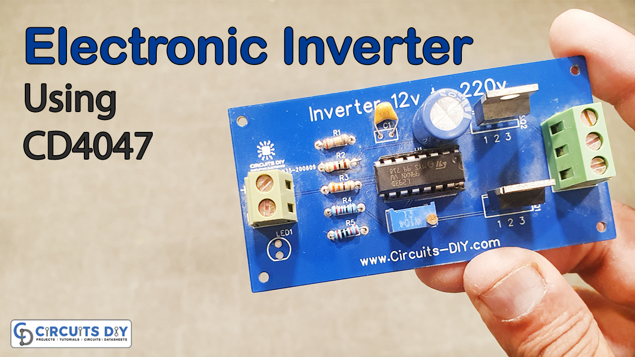
Now, coming towards the definition, inverters are simple electronic devices that can convert a DC signal into an AC signal of the desired voltage level. In addition, they are easy to design, build and assemble. Also, they are relatively inexpensive. So, to understand the better concept of an inverter, we will see the process of building a simple 12V DC to 220V AC inverter circuit. There are numerous ways to make the inverter circuit. But, in this tutorial, we are using CD4047 IC for this purpose.
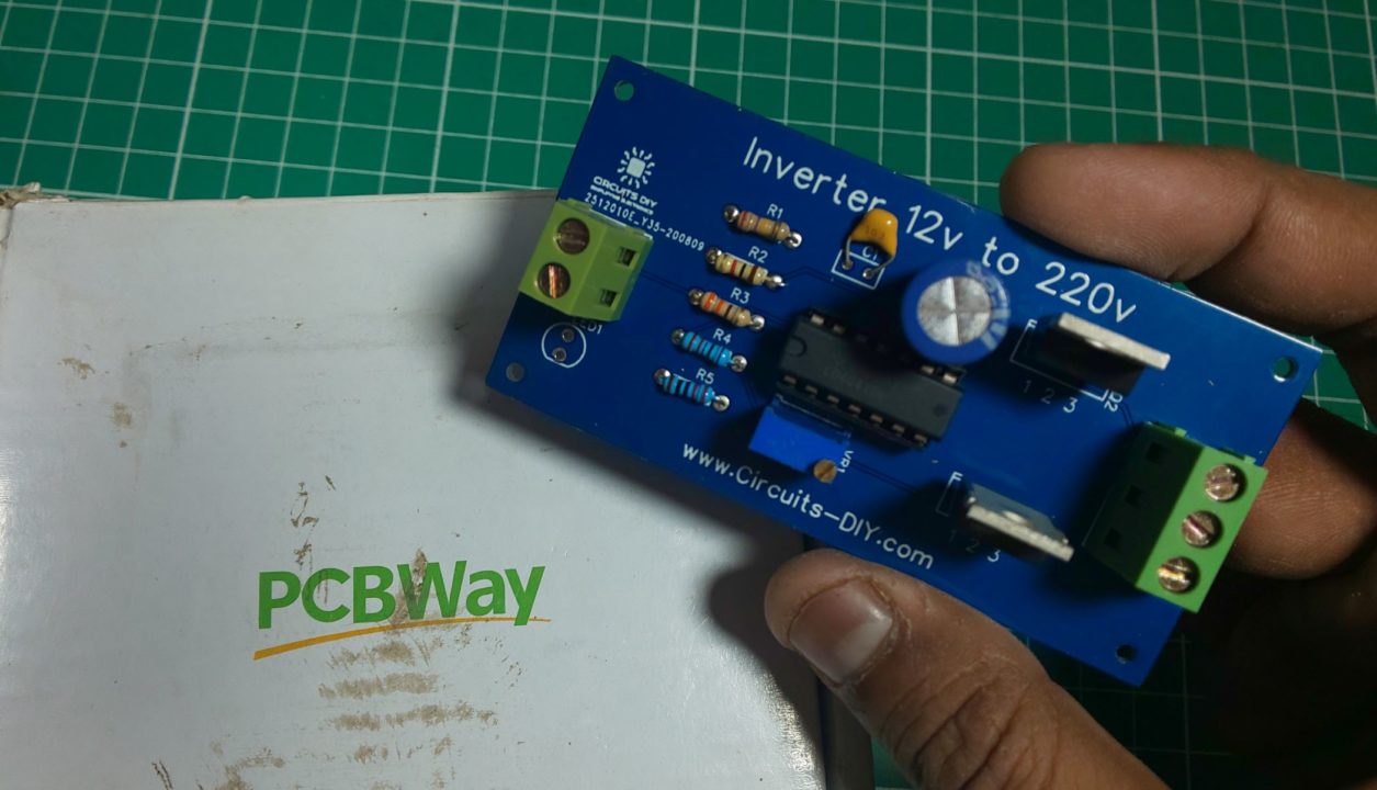
PCBWay commits to meeting the needs of its customers from different industries in terms of quality, delivery, cost-effectiveness, and any other demanding requests. As one of the most experienced PCB manufacturers in China. They pride themselves to be your best business partners as well as good friends in every aspect of your PCB needs.
Hardware Components
The following components are required to make the Inverter Circuit
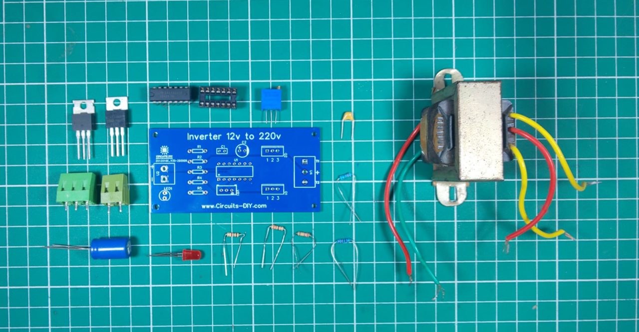
| S.no | Component | Value | Qty |
|---|---|---|---|
| 1. | Multivibrator IC | CD4047 | 1 |
| 2. | N – channel MOSFET | IRFZ44N | 2 |
| 3. | Transformer | Step up/12V 3A – 220V | 1 |
| 4. | Test Bench Oscilloscope with probes | – | 1 |
| 5. | Potentiometer | 100K | 1 |
| 6. | Inverter PCB | – | 1 |
| 7. | LED | 5mm/3.5V | 1 |
| 8. | Capacitor | 1000uF, 10nF | 2 |
| 9. | Resistors | 1K, 390K, 330 Ohm, 220 Ohm | 5 |
| 10. | Bulb | 220V/LED | 1 |
| 11. | Soldering Iron | 45W – 65W | 1 |
| 12. | Soldering Wire with Flux | – | 1 |
| 13. | DC Battery | 12V | 1 |
| 14. | Battery clips | – | 1 |
| 15. | Jumper Wires | – | As per need |
CD4047 Pinout
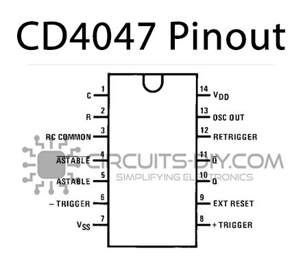
For a detailed description of pinout, dimension features, and specifications download the datasheet of CD4047
IRFZ44 Pinout
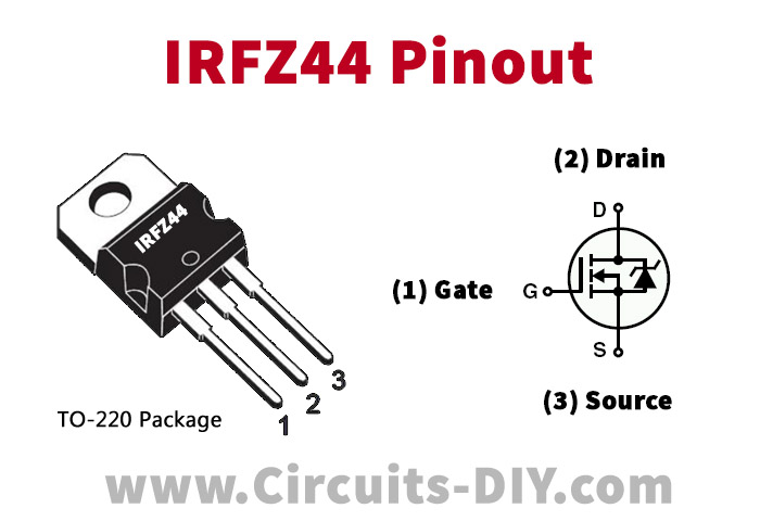
For a detailed description of pinout, dimension features, and specifications download the datasheet of IRFZ44
Inverter Circuit
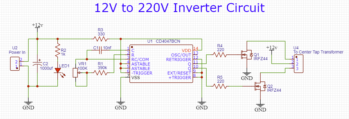
Working Explanation
In this circuit, the IC CD4047 is the central element. The IC is wired as an astable multivibrator. This has been achieved with the help of a potentiometer VR1 in the circuit. By varying this potentiometer and capacitor C1, one can get different ranges of output pulses at pin 10 and 11 of an IC. On the other hand, drain pins of Mosfets are wired with the secondary of the transformer in the circuit. And, source pins are connected to the negative terminal of the battery. Therefore, when the alternate pulses reach pin 10 and 11 of an IC, then, it drives the Mosfets. Hence, it forced the secondary winding to induce the alternate magnetic fields. As a result, the magnetic field produces a high alternate voltage of around 220 Volts.
Applications
- They are utilized in solar power systems
- An inverter is the basic building block for SMPS – switch mode power supply.
- They are used by devices such as Centrifugal fans, pumps, mixers, extruders, and test stands. conveyors, metering pumps. and Web-handling equipment






1 thought on “12v DC to 220v AC Inverter Circuit using CD4047 IC”
Comments are closed.