Introduction
To understand electronic devices and circuits, a power supply is generally considered the basic electronic circuit. We have seen that many junior students of electronic engineering start their circuit designing by making this circuit. Basically, the power supply is the circuit that converts the Alternating current power into direct current power. the circuit includes the voltage regulator circuits and the bridge rectifier circuits. Hence, to understand the whole circuitry, in this tutorial, we are going to Make a “12v and 5v Dual Power Supply”. As the name implies, it gives the two DC outputs at the load.
Hardware Required
| S.no | Component | Value | Qty |
|---|---|---|---|
| 1. | Step down transformer | 0-15V AC | 1 |
| 2. | Bridge Rectifier module | 1 | |
| 3. | Regulator IC | LM7812 | 1 |
| 4. | Regulator IC | LM7805 | 1 |
| 5. | LED | 2 | |
| 6. | Capacitors | 1000µF, 0.1µF, 100µF | 1, 2, 1 |
| 7. | Resistor | 2KΩ, 1KΩ | 1, 1 |
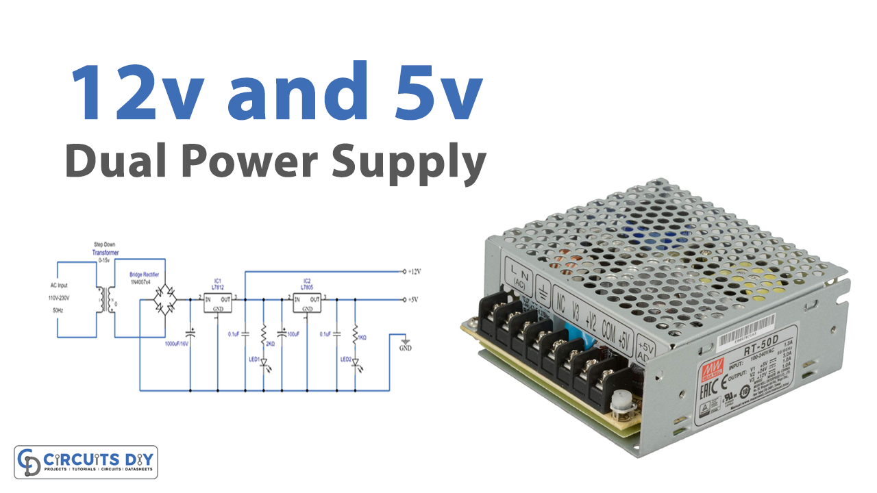
Circuit Diagram
Working Explanation
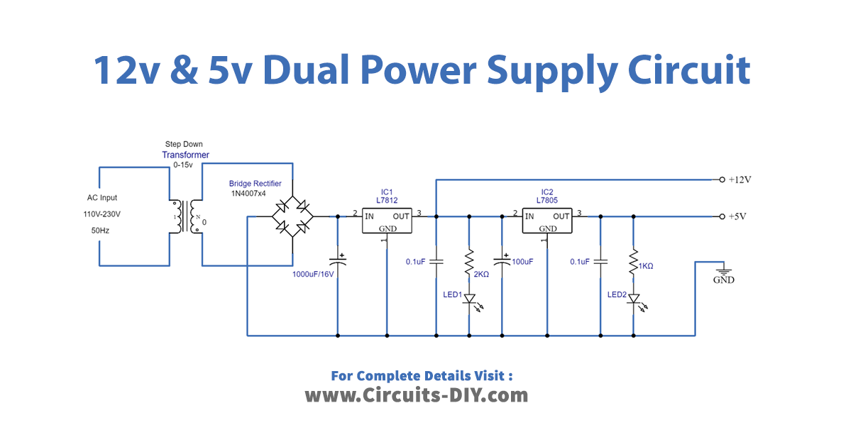
To make the 12v and 5v Dual Power Supply, the first step is to use the step-down transformer that decreases 230V into 15 V, then there is the full-bridge rectifier circuit that rectifies the AC voltage but it may have ripples which are filtered by the capacitor C1. now this voltage is provided at the input pin of the L7812 IC which gives the 12V DC-regulated output. And, LED 1 indicates the presence of the 12V. But, since we are making a dual supply, therefore for the other 5V, we have used the LC805 IC which gives the 5V regulated supply to the high-frequency ripple filtering capacitor C4, which after filtration gives the output of 5V, indicated by the LED 2.
Application and Uses
- Different electrical circuits.
- Computers.
- Solar panels.
- Televisions.
- Printers.
- Electrical vehicles.
- Medical equipment, etc.


