To make the 100 Watt MOSFET Power amplifier, you first need to know the basics of MOSFET and the power amplifier. And, to understand the power amplifier you have to know about the amplifiers. Generally, amplifiers are circuits that amplify the input audio signals at the output. Though, the amplifier circuits are of two kinds. The preamplifiers and the power amplifiers. Preamplifiers boost the weak signal. While power amplifiers, boost the line-level signals. Its stage comes after the preamplifiers.
Now coming towards the MOSFET. Mosfet is the metal oxide field-effect transistor. Commonly, used in two modes, as a switch or as an amplifier. It has three external terminals, which are Gate, drain, and source. Therefore it can be used in different configurations. To use the MOSFETs as an amplifier, or must be biased in a way that the majority of Carriers flow from source to drain.
Hardware Components
The following components are required to make 100W Power Amplifier Circuit
| S.no | Component | Value | Qty |
|---|---|---|---|
| 1. | Transistor | MJE340, MJE350 | 2, 2 |
| 2. | Transistor | BC556 | 4 |
| 3. | Electrolytic Capacitor | 100uf, 47uf | 1, 1 |
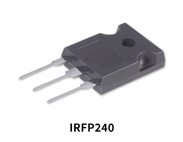
| 4. | MOSFET | IRFP9240 | 1 |
| 5. | Resistor | (0.33, 100, 470) ohms, 1K, 2.2K, 3.9K, 10K, 27K, 47K | 2, 3, 2, 1, 1, 2, 2,1,2 |
| 6. | Potentiometers | 100 ohms, 3K | 1, 1 |
| 7. | Ceramic Capacitor | 2.2uf, 100nf, 330pf, 18pf | 1, 2, 1, 1 |
| 8. | 3A fuse | – | 2 |
| 9. | Speaker | – | 1 |
| 10. | Dual power supply | 45V | 1 |
IRFP9240 Pinout
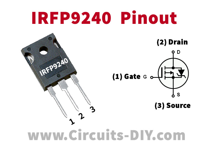
For a detailed description of pinout, dimension features, and specifications download the datasheet of IRFP9240
BC556 Pinout
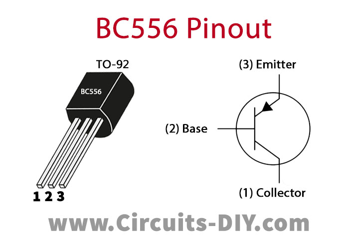
For a detailed description of pinout, dimension features, and specifications download the datasheet of BC556
MJE350 Pinout

For a detailed description of pinout, dimension features, and specifications download the datasheet of MJE350
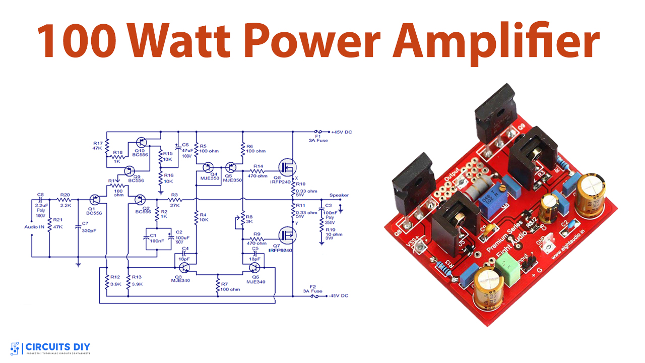
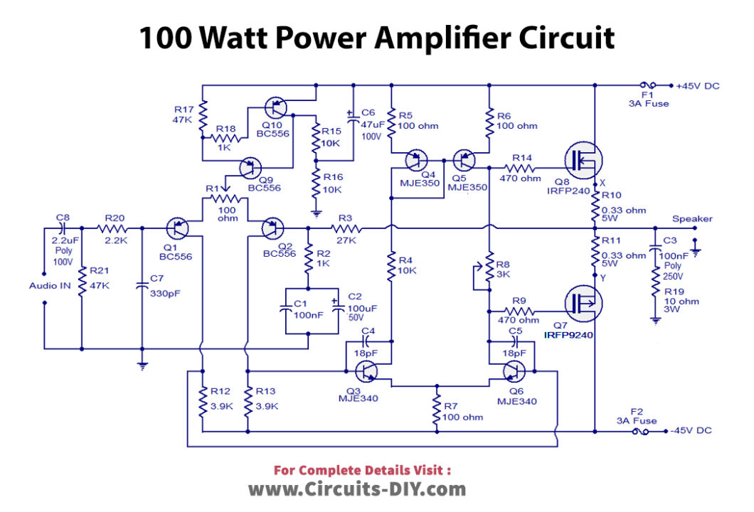
100W Power Amplifier Circuit
Working Explanation
In the MOSFET Power Amplifier circuit, capacitor C8 is the input decoupling capacitor. R20 is used to restrict the input current for transistor Q1. Resistor R3 and R2 are used to set the gain. While R1 is used to adjust the output voltage. Q7 and Q8 transistors make the power amplifier of class AB. The fuses are used in the circuit on a safe basis.
Application and Uses
Some of the applications are:
- Speakers
- Headphones
- RF transmitters, etc


