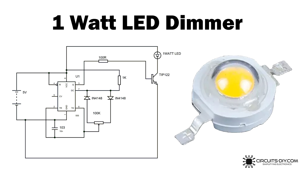
In this DIY, we are demonstrating the project of a 1 Watt LED Dimmer Circuit. LED DIMMER has mainly been designed to generate variable voltage over a fixed voltage, using a PWM (pulse width modulation) circuit based on the 555 timer IC. Below is the form of PWM. First, consider a single circuit, as seen in the figure below, before constructing a 1-Watt LED dimmer circuit.

Hardware Components
The following components are required to make LED Dimmer Circuit
| S. No | Component | Value | Qty |
|---|---|---|---|
| 1 | LED | 1W | 1 |
| 2 | IC | NE555 | 1 |
| 3 | Resistor | 1K, 100R | 1, 1 |
| 4 | Darlington Transistor | TIP122 | 1 |
| 5 | Capacitor | 10nF or 22nF | 1 |
| 6 | Potentiometer | 100K | 1 |
| 7 | Diode | IN4148 | 2 |
NE555 IC Pinout

For a detailed description of pinout, dimension features, and specifications download the datasheet of 555 Timer
TIP122 Pinout
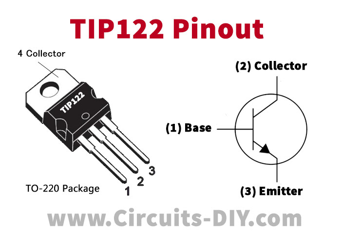
For a detailed description of pinout, dimension features, and specifications download the datasheet of TIP122
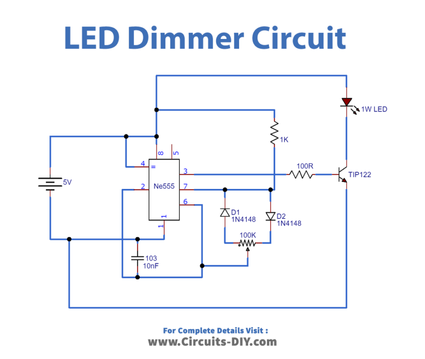
LED Dimmer Circuit
Working Explanation
All PWM generation occurs due to the variations in the charge and discharge times of the device’s capacitor. Remember now that the pot is adjusted, and the resistance is split into 25 K on one side and 75 K on the other. The charge can now occur only through the resistance portion of 75 K due to diode D2 through the capacitor. 555 TIMER IC outputs are high during the charging time—the capacitor discharges when the capacitor charges to a potential.
Therefore, every time we adjust the potentiometer, we vary; PWM’s performance is different in on and off times.
Now, this PWM signal is fed into the transistor base to regulate the high current load. The effect is that, now that you can draw a maximum of 50 Hz, your human eye can not catch the framework, and so the light will be on for just eight. The light looks dim over the initial intensity of the human eye. The effect is that it is ON for 8ms, and the human eye can not catch the frame. Back then, it seems to be continuous. The purpose of the project is thus accomplished.
Applications and Uses
The LED Dimmer Circuit is used in:
- backlight for smartphones
- Portable GPS navigation systems