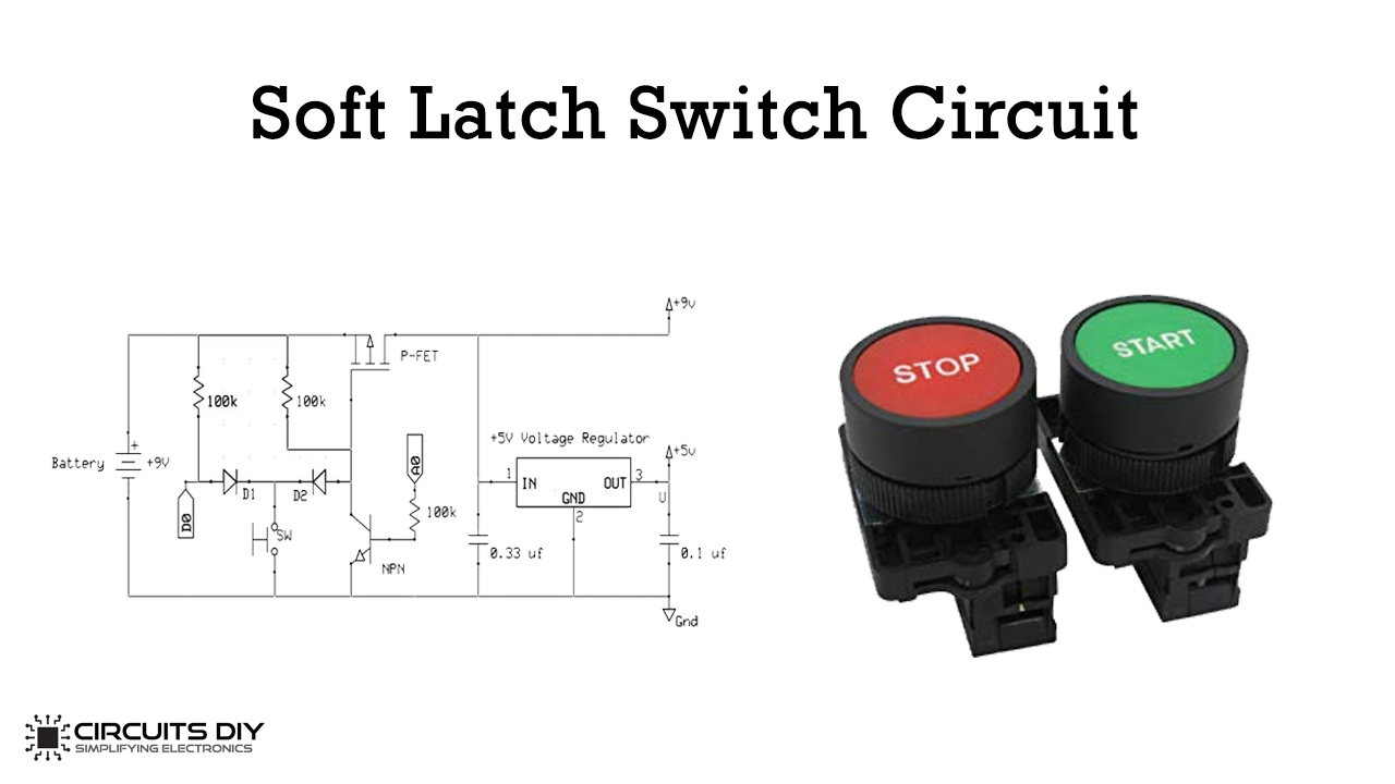
In this tutorial, we are going to make a simple “Soft Latch Switch Circuit“. A latch circuit can ‘keep’ the circuit in either an on or off state until it applies an external signal to it. The latch circuit maintains its position (either on or off) even after it removes the input signal and can store one bit of information as long as it supports the device.
The soft latch power switch allows one button to perform three tasks – Power on the micro-controller, act as an input to the micro-controller and turn off the micro-controller. Also, the soft latch power switch allows the micro-controller to power itself off.
It is excellent for situations where the user may not power the device off. Still, you need to conserve the battery if it receives no input within the desired time; the micro-controller powers itself down.
Hardware Components
The following components are required to make Soft Latch Switch Circuit
| S.No | Component | Value | Qty |
|---|---|---|---|
| 1. | Breadboard | – | 1 |
| 2. | Arduino With a Cable | Uno R3 | 1 |
| 3. | Diode | 1N4007 | 2 |
| 4. | P-Channel FET | STP12PF06 | 1 |
| 5. | NPN Transistor | 2N3904 | 1 |
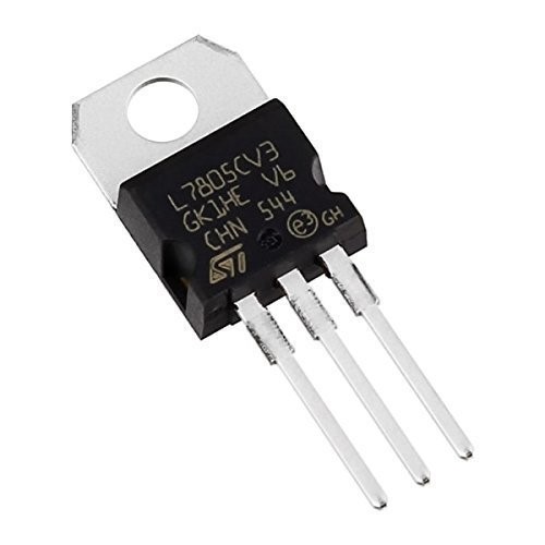
| 6. | Regulator IC | LM7805 | 1 |
| 7. | Momentary Switch | – | |
| 8. | Resistor | 100k | 3 |
| 9. | Ceramic Capacitor | 0.33,0.1uF | 1,1 |
| 10. | Proto-Board | – | 1 |
LM7805 Pinout
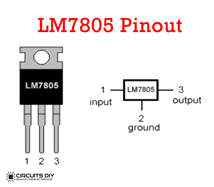
For a detailed description of pinout, dimension features, and specifications download the datasheet of LM7805
2N3904 Pinout
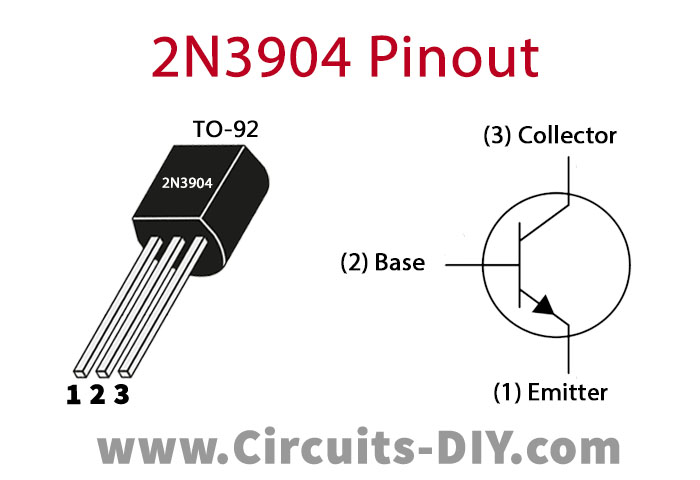
For a detailed description of pinout, dimension features, and specifications download the datasheet of 2N3904
Soft Latch Switch Circuit
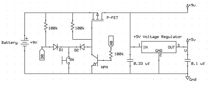
Construction
Connect all on your proto-board, as shown in the diagram. Note that “A0” and “D0“connect to the micro-controller and the + 5V and ground (to the right of the diagram). If desired, you can connect the output +9V at the top right to additional required circuits. Otherwise, connect it to the voltage regulator.
Working Explanation
When the power is off, and you press the switch, it activates the P-FET and supplies the + 9V to the linear voltage regulator. The regulator then transfers +5 V to the micro-controller, and it will turn on. It is essential that your software immediately sets the “A0” pin to the high output. If done correctly, the voltage on this pin will activate the NPN transistor and latch the power circuit on. While powered on, you can set up the “D0” pin and use it as input. In this prototype, when you momentarily press the switch, the system responds by playing a beep.
If you hold the switch down for at least 2 seconds, the micro-controller plays a longer beep and sets pin “A0” to a low output. It will release the latch and will turn off the micro-controller when it releases the switch. If you do not press the switch for 30 seconds, the microcontroller will stop automatically.
Application
- The soft latch circuit is suitable for battery-operated portable instruments because it has zero voltage in the off state.
- We can use a soft latch circuit to auto-turn off ESP32, ESP8266, Arduino, or any other microcontrollers. The latch circuit can be handy in an alarm circuit.