TV Remote jammer circuit is one of the simple and cool projects in our daily life. The TV remote jammer project uses a NE555 timer IC that generates a constant signal which interferes with the remote control signal and blocks signal receiving at the receiver of the TV as the Television remotes are based on IR sensors.
The idea behind the TV Remote jammer project is that this will permit any individual to watch his or her favorite series and no one can disturb by changing the channel

Hardware Components
The following components are required to make TV Remote Jammer Circuit
| S. No | Component | Value | Qty |
|---|---|---|---|
| 1. | IC | 555 Timer | 1 |
| 2. | NPN Transistor | 2N2222 | 1 |
| 3. | Potentiometer | 100k | 1 |
| 4. | Resistors | (220 ohms, 1K, 10K | 1, 1, 1 |
| 5. | Ceramic Capacitors | 10nF | 1 |
| 6. | LED | 3 | |
| 7. | Battery | 9v | 1 |
555 IC Pinout

For a detailed description of pinout, dimension features, and specifications download the datasheet of 555 Timer
Circuit Diagram
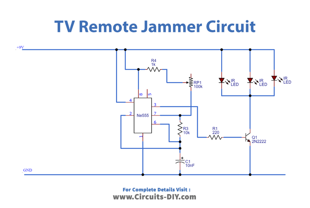
Working Explanation
I am using NE555 Timer IC in my project TV Remote jammer which is operating in astable mode. The astable mode of 555 timer IC works as an oscillator and produces square waves depending on the values of resistors and capacitors you are using. The underlying fact is that the majority of television remotes use IR (infrared) rays technology in which the transmitter which sends the signal is deployed at the remote and the receiver which receives the signal is installed at the TV end.
Now What happens is that different signals are being transmitted by the transmitter of the remote to the receiver of the television and for every signal, there is a unique pattern generated. The function of the TV remote jammer circuit is to puzzle the receiver of the TV by generating steady pulses that provide no useful information to the receiver and as a conclusion, no decision can be made by the receiver.