
The temperature sensor is very useful in different ways. It can activate or deactivate any kind of device by observing a temperature. Its other application is a fire alarm circuit. So, In this tutorial, we will design a simple Temperature Sensor circuit using the LM35 IC.
If the temperature rises to a particular level the red Led glows which indicates the high temperature. While in other cases if the temperature falls below, the green Led glows which shows the low temperature.
Hardware Components
The following components are required to make Temperature Sensor Circuit
| S.No | Component | Value | Qty |
|---|---|---|---|
| 1. | Breadboard | – | 1 |
| 2. | Battery | 9v | 1 |
| 3. | Potentiometer | 2k | 1 |
| 4. | Resistors | 10k, 470 ohms | 1, 2 |
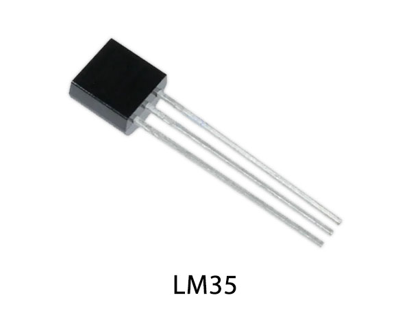
| 5. | Temperature IC | LM35 | 1 |
| 6. | op-Amp IC | LM741 | 1 |

For a detailed description of pinout, dimension features, and specifications download the datasheet of LM35
Temperature Sensor Circuit

Working Explanation
LM35 is an application of a digital thermometer and it also measures the temperature. It is a very famous and inexpensive temperature sensor. Its output varies according to the temperature around it. The range of the LM35 IC lies between -55 degrees to 150 degrees. If the temperature is 0 degrees the output will also be 0V. For every 10 degrees rise in temperature, there will be a rise of 10mv.
The two LEDs are used at the output to indicate the high and low temperatures. As the temperature rises, it increases the voltages of a comparator, The comparator then amplifies the difference of voltages and indicates high or low temperature by triggering the Led.
Application
- Measuring the temperature of an environment.
- Monitoring Battery temperature.
- Providing thermal shutdown for a system when required.