This tutorial explains the working of a Push-button. It also explains the use of the push-button circuit. In the tutorial, a push-button controls the LED at the output. Basically, a push-button is a type of switch which completes the circuit as it is pressed. So its working makes its usage very much important in most of the systems for triggering inputs.
It uses a spring that takes it back to initial or off when the button is released. The digital circuit operates in two voltages i.e high or low. So the input devices like these should be able to produce both the conditions.
Hardware Component
Following are the necessary hardware items required for Push Button Circuit:
| S.No | Component | Value | Qty |
| 1. | Button | – | 1 |
| 2. | LED | – | 1 |
| 3. | Resistor | 330 Ohm | 1 |
| 4. | Battery with Clip | 9V | 1 |
| 5. | Breadboard | – | 1 |
| 6. | Jumper Wires | – | 1 |
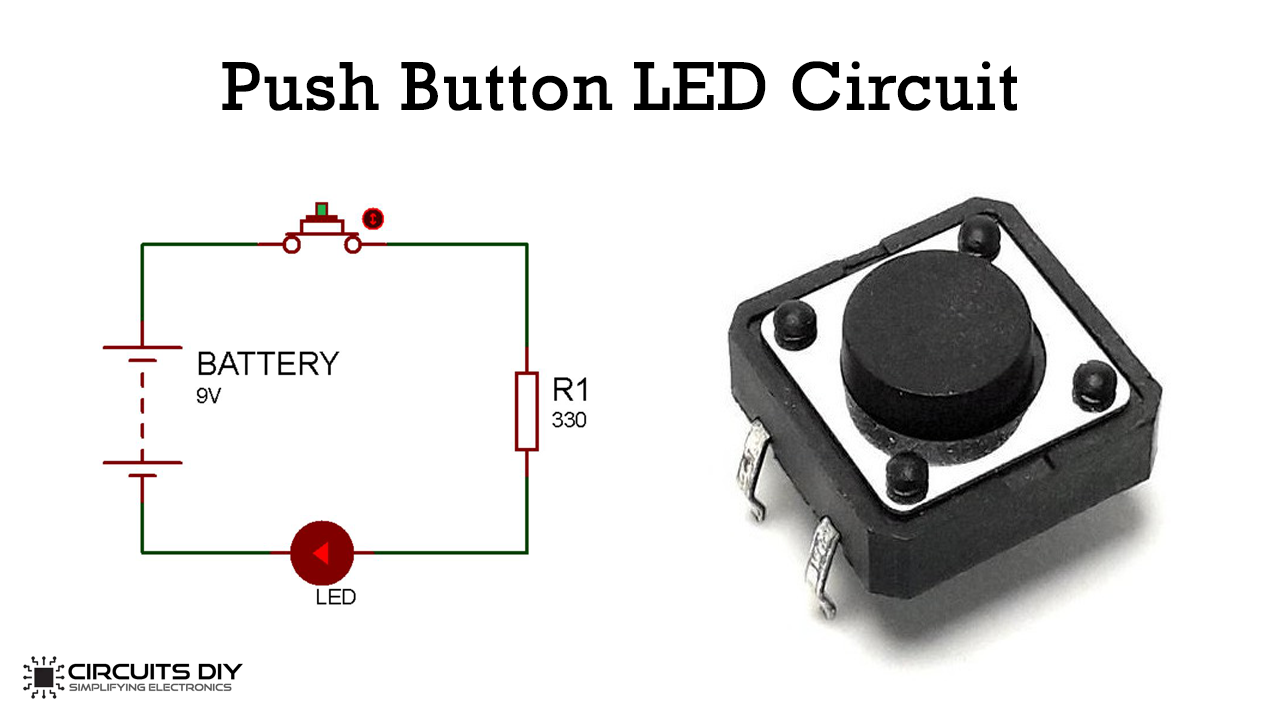
A push-button is a kind of a circuit that works on a simple mechanism i.e “push to make”. Initially, the push-button remains in off-state which is also called a normally open state. As the button is pressed, it makes the circuit and allows the current to pass through. Normally plastic or some metals make up their bodies. It comprises of four legs.
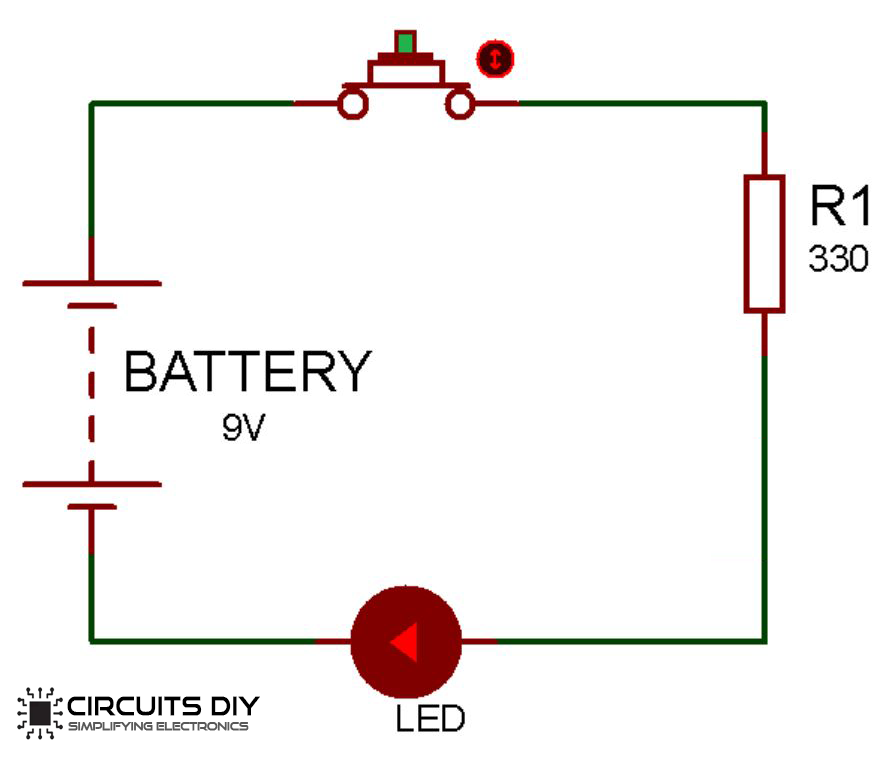
As long as the button is pressed it makes the circuit and allows the current to pass through it. Whenever the button is released it breaks the circuit again. One leg of the push-button is connected with supply while the other is connected with the LED with the resistor at the output. So as the button is pressed it conducts the current which glows the LED. And as it is released it stops the supply.
Circuit Diagram