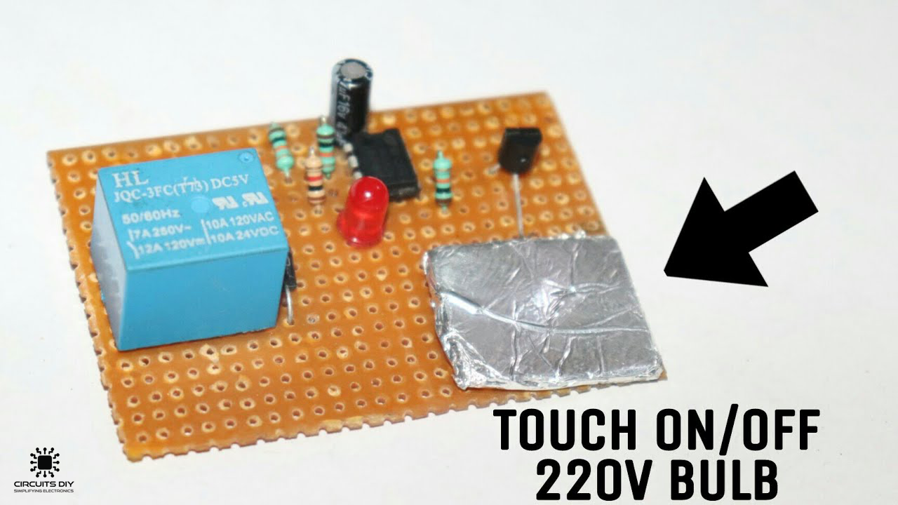
What is a Latching Touch Switch?
A latching touch switch is a simple capacitive tactile sensor that retains its state (On/Off), after being pressed. These types of switches function by measuring a small electrical charge (Vsig) that gets transferred from your body to the switch itself and happens more or less the instant you make clean contact with it. Latching touch switches have a wide array of applications & are used in almost every AC/DC consumer appliance such as lighting fixtures, cleaning appliances, and ventilation systems, etc. So, In today’s tutorial, we are going to design a simple Latching Touch Switch using a NE555 Timer IC.
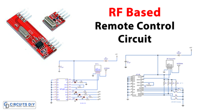
The heart of this circuit is a NE555 precision timer IC. The IC possesses an oscillation frequency ranging from 670 to 680Hz. Here, the IC is operating in a bi-stable multi-vibrator mode. Basically, a bi-stable multi-vibrator stays low until a trigger signal is applied and it stays high until a reset signal is applied. This mode is ideal to be used in applications such as latches & memory cells since the output of the bi-stable multi-vibrator remains at a single state (either 5V or 0V) until the trigger signal is applied.
JLCPCB is the foremost PCB prototype & manufacturing company in china, providing us with the best service we have ever experienced regarding (Quality, Price Service & Time).
Hardware Components
The following components are required to make the Latching Touch Switch Circuit
| S.no | Component | Value | Qty |
|---|---|---|---|
| 1 | IC | NE555 Timer | 1 |
| 2 | Relay | 12V/SPDT | 1 |
| 3 | Transistor | 2n2222 | 1 |
| 4 | LED | 5mm, 3.5V | 1 |
| 5 | Bulb | AC, 220V/50Hz | 1 |
| 6 | Diode | 1N4007 | 1 |
| 7 | Capacitor | 47uF | 1 |
| 8 | Resistor | 10K, 1K | 4 |
| 9 | Wall Outlet | 220V AC | 1 |
| 10 | Soldering Iron | 45W – 65W | 1 |
| 11 | Soldering Wire with Flux | – | 1 |
| 12 | DC Battery with clip | 12V | 1 |
| 13 | Veroboard | – | 1 |
| 14 | Silver/Aluminium foil | – | As per need |
| 15 | Card paper/Cardboard | – | As per need |
| 16 | Jumper Wires | – | As per need |
NE555 Timer Pinout
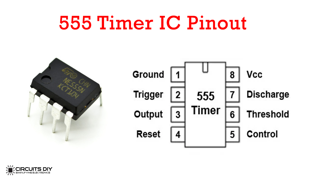
For a detailed description of pinout, dimension features, and specifications download the datasheet of 555 Timer
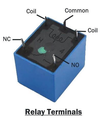
12V Relay Pinout
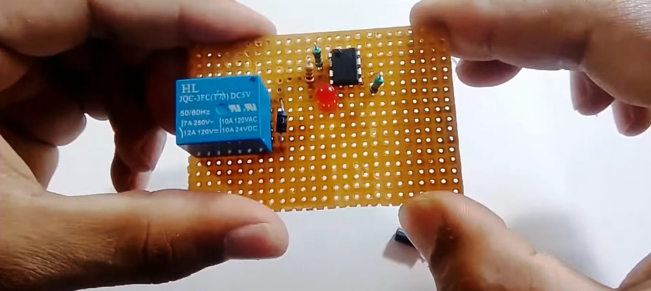
Latching Touch Switch Circuit
Useful Steps
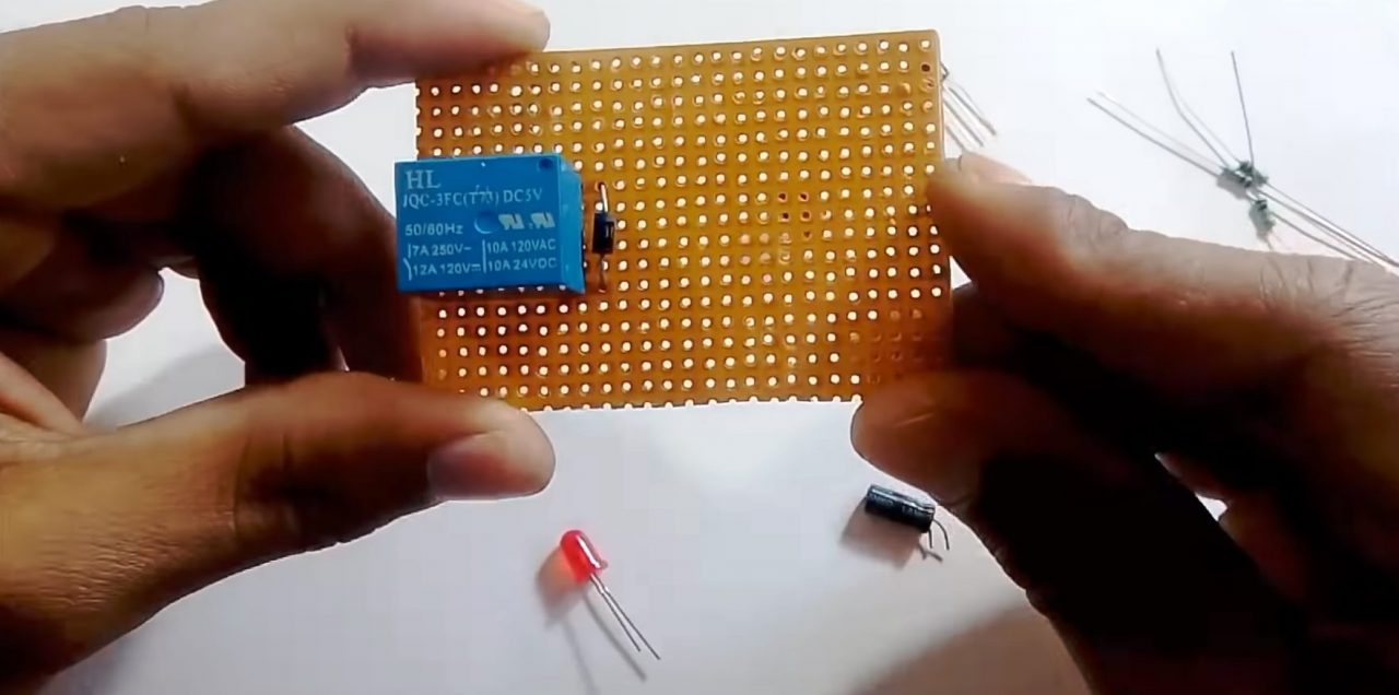
1) Solder a 12V relay on the Veroboard. After that, solder a 1N4007 diode with coil 1 & 2 terminals of the relay.
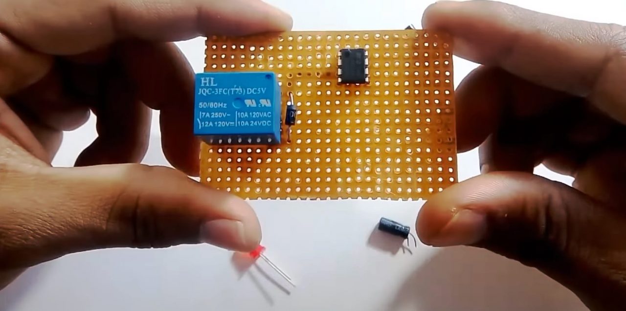
2) Solder NE555 timer IC on the Veroboard. After that, the solder the cathode terminal of the diode with pin 3 of the IC.
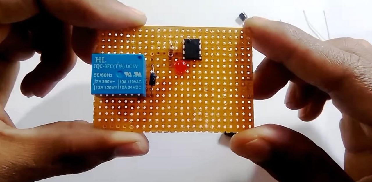
3) Solder the 1K resistor between pin 3 of the IC & the -ve terminal of the LED. After that, solder the +ve terminal of the LED with pins 4 & 8 of the IC.
4) Solder a 10K resistance between pin 2, 6 & 1 of the IC. After that, solder another 10K resistance between pins 2, 6 & pins 4, and 8 of the IC.
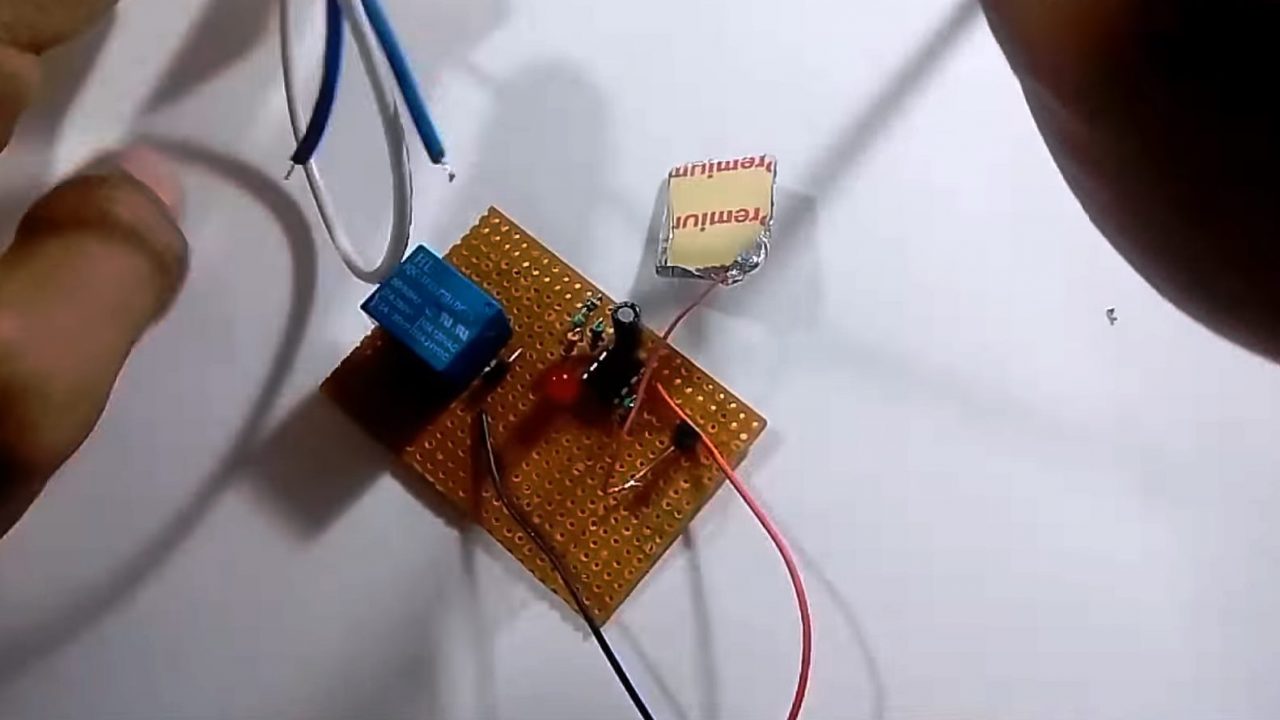
5) Wrap a piece of card paper with Aluminium foil & solder it to the base terminal of the 2N2222 transistor using a piece of wire. After that, solder the collector terminal of the IC with pin 6 of the IC.
6) Solder a 10K resistance between Pin 3 of the IC & the emitter terminal of the transistor. After that solder the +ve terminal of the 47uF capacitor with the emitter terminal of the transistor & the -ve terminal with pin 1 of the IC.
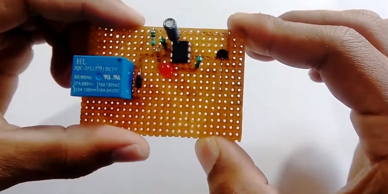
7) Solder the -ve terminal of the battery with pin 1 & +ve terminal with pin 8 of the IC.
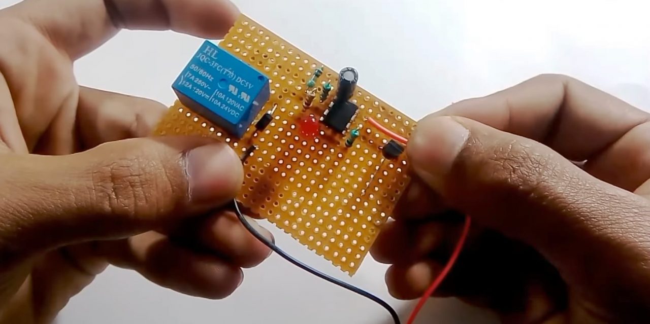
8) Complete the external relay circuit using a 220V AC outlet & any AC device (Bulb). Simply wire the Bulb -ve with NO terminal and +ve with the 220V supply. Then, ground the COM terminal along with the supply ground.
9) Power up & test the circuit.
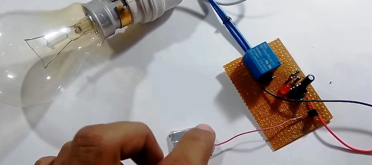
Working Explanation
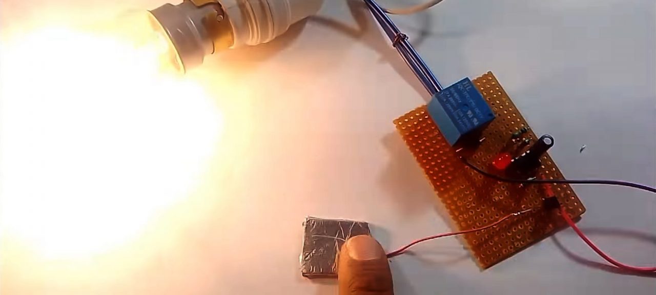
The working of this circuit is actually pretty simple. Here the NE555 timer IC is operating in bistable multivibrator mode. On touching the silver coated card piece. A small signal (Vsig) acts as the control signal at the base of the transistor 2n2222. The collector output from the transistor goes through a voltage divider circuit. The output of which serves to set both the threshold of the 555 timer IC (about ⅓ of the supply) & trigger input to the 555 timer IC. Since the 555 timer IC is operating in Bi-Stable multivibrator mode, the output remains set to HIGH (Latched) throughout the use of the circuit, until another triggering input resets the state of the IC.
The output from the NE555 timer IC moves on to energizing the coil terminals of the 12V relay. Here, we are using a diode (1N4007) to protect the circuit from any negative feedback. On energizing, the coil gets charged & makes the relay from NO to NC, completing any externally connected circuit. Always make sure that the rating of the relay is in accordance with the rating of the supply & the load.
Applications
- Used in various AC/DC appliances such as Bulbs, ceiling fans, & PCs, etc.