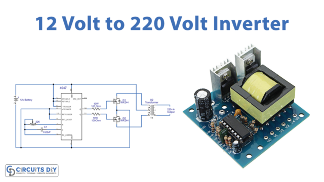
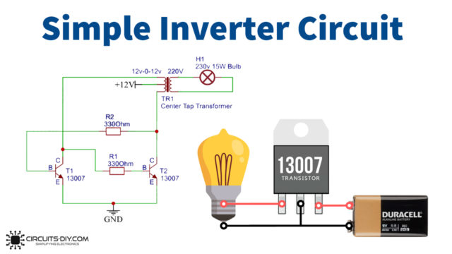
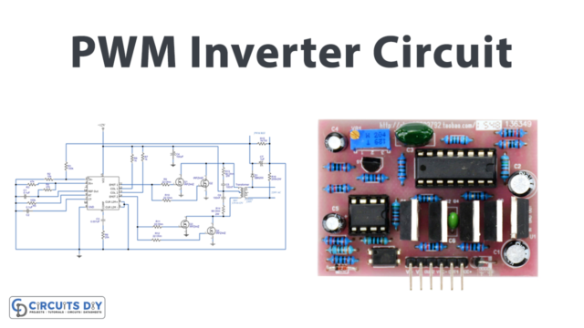
What is an Inverter Circuit?
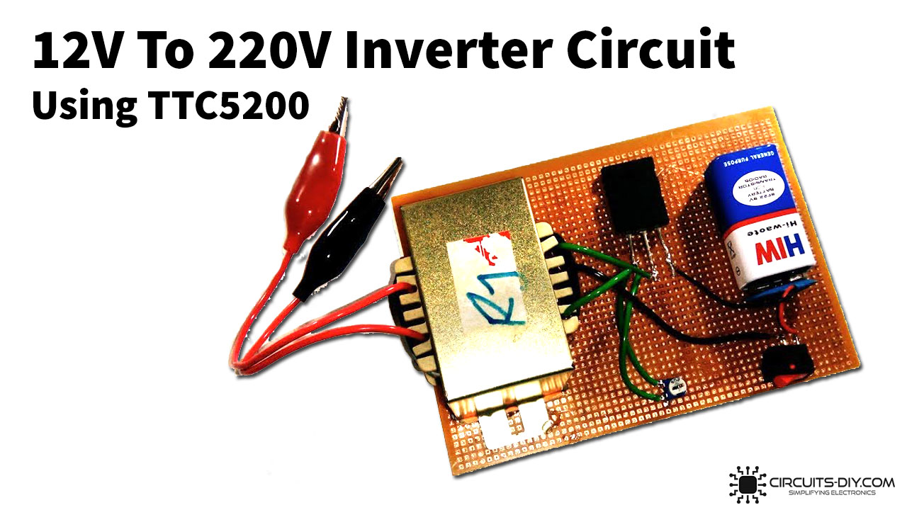
Inverters or Power inverters are simple electronic circuits that can convert a DC voltage signal into an AC signal of the desired voltage level. They serve as an important backup fail-safe in case of a power failure/blackout in places such as homes, offices & industries. They are easy to design, and build & are relatively inexpensive. So, In today’s tutorial, we are going to build a simple 12V To 220V Inverter Circuit Using a TTC5200 Power Transistor.
The main component of this inverter circuit is a TTC5200 NPN power transistor. It is a silicon NPN triple diffused type bipolar power transistor, offering a wide variety of features including ESD & thermal overload protection. It has a high collector output voltage of 230V. The TTC5200 transistor is generally used for power amplification applications.
JLCPCB is the foremost PCB prototype & manufacturing company in china, providing us with the best service we have ever experienced regarding (Quality, Price Service & Time).
Hardware Components
The following components are required to make 12V To 220V Inverter Circuit
| S.no | Component | Value | Qty |
|---|---|---|---|
| 1. | Transformer | Step-up, CT, 12V/220V/3A, 50Hz | 1 |
| 2. | Power Transistor | TTC5200 | 1 |
| 3. | Toggle switch | – | 1 |
| 4. | Potentiometer | 5KOhms | 1 |
| 5. | Wire Cutter | – | 1 |
| 6. | LED Bulb | 220V | 1 |
| 7. | Soldering Iron | 45W – 65W | 1 |
| 8. | Soldering wire with flux | – | 1 |
| 9. | DC Battery | 9V | 1 |
| 10. | Battery Clips | – | 1 |
| 11. | Veroboard | – | 1 |
| 12. | Jumper Wires | – | As per need |
TTC5200 Pinout
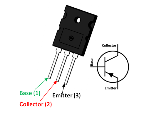
For a detailed description of pinout, dimension features, and specifications download the datasheet of TTC5200
Useful Steps
Follow the steps as shown in the video above
1) Solder the +12V terminal of the CT transformer with the collector of the TTC5200 transistor.

2) Solder the -12V terminal of the CT transformer with the 5K pot.

3) Solder base terminal of the power transistor with 5K pot.

4) Solder the +ve terminal of the 9V battery with the +ve terminal of the toggle switch & the -ve terminal of the battery with the emitter terminal of the transistor.

5) Solder the GND terminal of the CT transformer with the -ve terminal of the toggle switch.

6) Power up & test the circuit using a 220V LED bulb or a multimeter.


Working Explanation
The working of this 12V To 220V Inverter circuit is actually pretty simple. A 9V DC is fed to the base terminal of the TTC5200 power transistor. The collector output from the transistor is then boosted to a 12V, 3A DC PWM signal of adequate wattage.
This DC signal is then fed to a 12V/220V 3A step-up transformer, which boosts the input 12V PWM to a 220V noisy sine wave. The output of the transformer is then connected to an external load such as an LED bulb. You can connect an LC circuit in parallel to the output of the transformer to condition the signal into a pure sine wave.
Applications
- They are generally used as primary backup power in case of a blackout.


